ALLPCB


Short circuits in printed circuit boards (PCBs) can cause device failures, reduced performance, or even permanent damage to components. For engineers, detecting and resolving these issues quickly is critical to ensuring reliable electronics. In this blog, we explore the tools and techniques used to identify short circuits in PCBs, offering practical insights to streamline your troubleshooting process. From visual inspections to advanced testing methods, we'll guide you through actionable steps to maintain high-quality PCB performance.
Understanding Short Circuits in PCBs
A short circuit occurs when an unintended electrical connection forms between two points in a circuit, allowing current to bypass the intended path. This can result from solder mask bridges, manufacturing defects, or environmental factors like dust or moisture. Short circuits are particularly problematic in high-density PCBs, where traces are closely spaced, increasing the risk of unintended connections. For instance, in surface-mount technology (SMT) boards, solder bridges between pads can create shorts, leading to failures. Detecting these issues early is essential to prevent costly rework or field failures.
Visual Inspection: The First Line of Defense
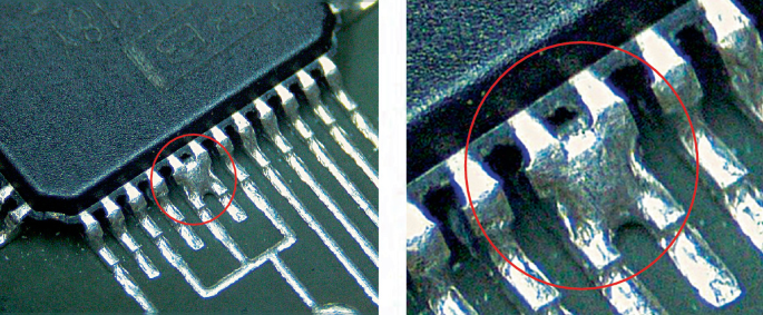
Visual inspection is often the first step in detecting short circuits, as many issues are visible to the naked eye or under magnification. Start by examining the PCB under bright lighting for obvious signs like burn marks, damaged components, or excess solder. For denser boards, use a magnifying glass or a low-magnification microscope to inspect solder joints and traces. Look for common defects such as solder bridges, tombstoning (when a component lifts during soldering), or tin whiskers (microscopic conductive filaments that can cause shorts).
While visual inspection is cost-effective and quick, it has limitations. Hidden shorts, such as those in internal layers of multilayer PCBs, may not be visible. Additionally, human error can lead to missed defects, especially in complex designs. Despite these challenges, visual inspection remains a critical starting point for troubleshooting.
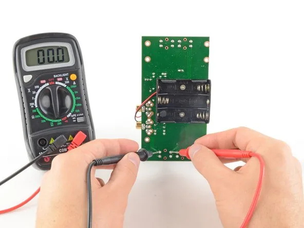
Multimeter Testing: Pinpointing Electrical Shorts
A multimeter is a go-to tool for detecting short circuits by measuring continuity or resistance between points in a circuit. Set the multimeter to continuity mode, which beeps when a connection is detected, indicating a potential short. For example, place one probe on a ground point and the other on a signal trace or power net to check for unintended connections. A resistance reading below 10 ohms between two points that should be isolated often confirms a short.
For precise measurements, use a multimeter with milliohm sensitivity. In a typical PCB with 35μm copper foil and 1mm trace width, the resistance of a trace is approximately 5 milliohms per centimeter. If a component shows a resistance significantly lower than expected (e.g., tens of milliohms), it may be shorted. Be cautious when probing dense boards to avoid misinterpreting shared ground connections as shorts.
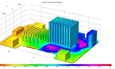
Thermal Imaging: Identifying Hotspots
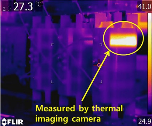
Short circuits often cause excessive current flow, leading to localized heating. A thermal camera can detect these hotspots, making it an effective tool for pinpointing shorts, especially in powered-up boards. For instance, a shorted trace may heat up to 50-70°C, significantly higher than the surrounding areas, which typically remain below 30°C under normal operation.
To use a thermal camera, power the PCB carefully and observe the board through the camera's display. Focus on areas with abnormal temperature spikes, then verify the findings with a visual inspection or multimeter test. Thermal imaging is particularly useful for detecting shorts in multilayer boards, where internal layer defects are not visible. However, thermal cameras can be expensive, and interpreting results requires expertise to avoid false positives from naturally warm components like power regulators.
Advanced Tools: Time Domain Reflectometry (TDR) and X-Ray Inspection
For high-density or multilayer PCBs, advanced tools like Time Domain Reflectometry (TDR) and X-ray inspection offer deeper insights. TDR sends a high-frequency signal through a trace and measures reflections caused by impedance changes, such as those from a short. By analyzing the time delay of the reflected signal, TDR can locate a short within millimeters, even in internal layers. For example, a TDR system operating at 10 GHz can detect impedance discontinuities with a resolution of about 1 cm.
X-ray inspection, on the other hand, is ideal for identifying hidden defects like insufficient clearance between vias or solder bridges under ball grid array (BGA) components. Radiographic images reveal conductive paths that may cause shorts, such as excess solder or misaligned layers. While both TDR and X-ray inspection provide high accuracy, they require specialized equipment and trained operators, making them more suitable for critical applications or high-volume production.
In-Circuit Testing (ICT) and Flying Probe Testing
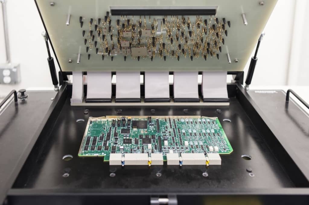
In-Circuit Testing (ICT) and flying probe testing are automated methods for detecting shorts in assembled PCBs. ICT uses a 'bed of nails' fixture with fixed probes to contact test points on the board, measuring electrical properties like resistance and capacitance. It can detect 98% of faults, including shorts, with high accuracy. For example, ICT can identify a short between two nets by detecting a resistance below 10 ohms where isolation is expected.
Flying probe testing, a fixtureless alternative, uses movable probes to test nodes on the board. It's ideal for low-volume or prototype boards, as it doesn't require custom fixtures. Both methods are highly effective but have trade-offs: ICT is faster but costly due to fixture development, while flying probe testing is slower but more flexible. Choosing between them depends on production volume and budget.
Recommened Reading: Introduction to PCB Testing: ICT, Flying Probe, and Functional Tests
Deep Learning and Automated Optical Inspection (AOI)
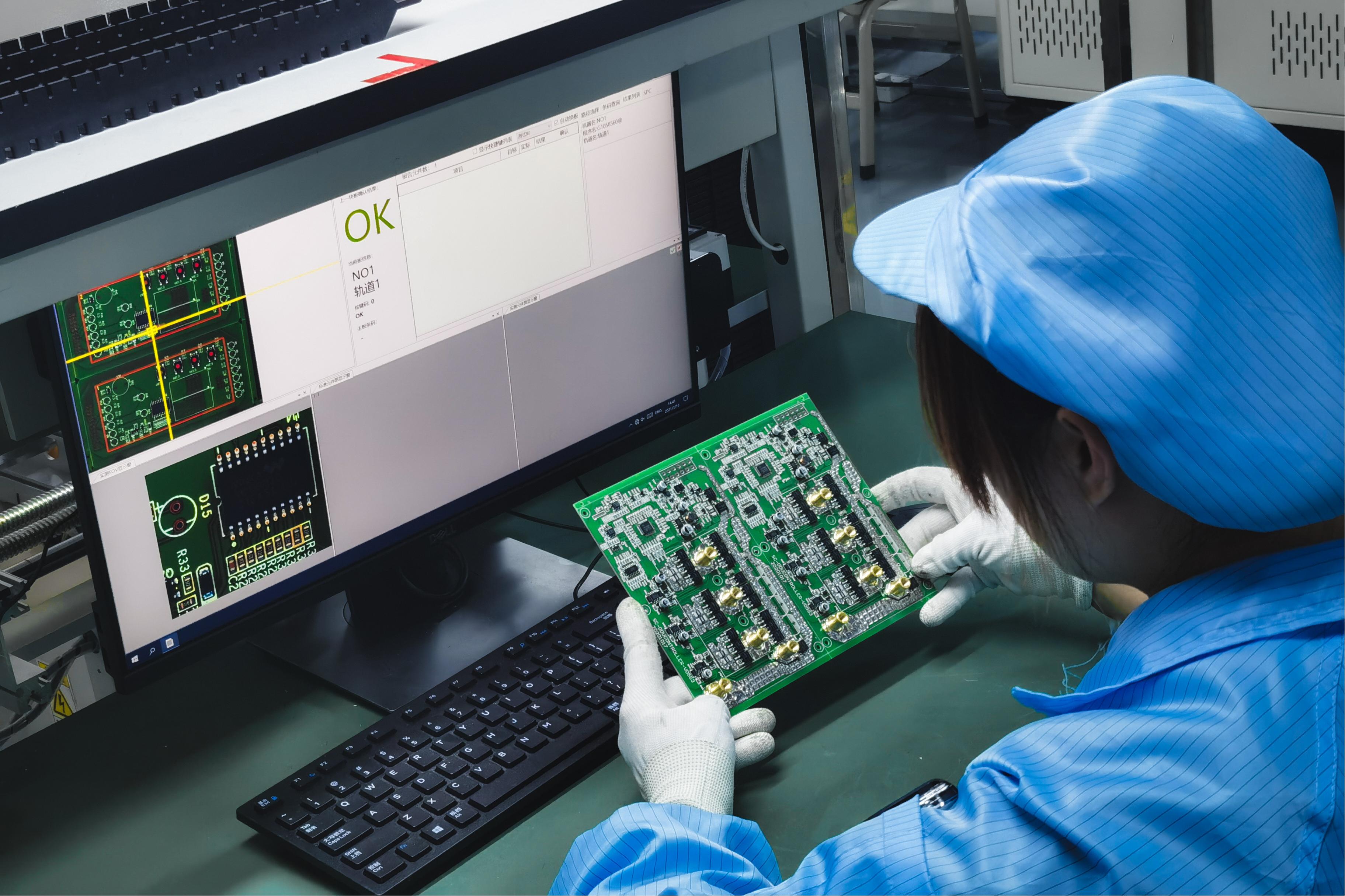
Automated Optical Inspection (AOI) systems use cameras and image processing to detect visible defects like solder bridges or misaligned components. Modern AOI systems integrate deep learning models, such as You-Only-Look-Once (YOLO) or Faster R-CNN, to classify defects with high accuracy. A 2022 study reported that a deep learning framework achieved a 98.1% mean average precision for PCB defect detection using low-resolution images, surpassing traditional methods.
AOI is fast and non-invasive, making it ideal for high-volume production. However, it's limited to surface defects and may miss internal shorts. Combining AOI with electrical testing methods like ICT ensures comprehensive defect coverage. For engineers, AOI provides a scalable solution to maintain quality without sacrificing speed.
Preventive Design Strategies to Minimize Shorts
While detecting short circuits is crucial, preventing them during the design phase saves time and resources. Use Design for Manufacturability (DFM) checks to ensure adequate spacing between traces and pads-typically at least 0.15 mm for high-density boards. Incorporate copper thieving to balance copper distribution and reduce warping, which can cause shorts. Additionally, specify plated-through-hole (PTH) clearances to avoid unintended connections between layers.
Simulate your design using PCB design software like OrCAD or Altium to identify potential short risks before fabrication. For example, a Design Rule Check (DRC) can flag traces with insufficient clearance, such as those below 0.1 mm, which are prone to bridging during soldering. By addressing these issues early, you reduce the likelihood of shorts in the final board.
How ALLPCB Supports Short Circuit Prevention and Detection
At ALLPCB, we understand the challenges engineers face in ensuring PCB reliability. Our advanced manufacturing capabilities, including high-precision SMT assembly and rigorous quality control, minimize the risk of short circuits during production. With quick-turn prototyping, we enable you to test and refine designs rapidly, catching potential issues early. Our global logistics ensure fast delivery, so you can iterate and troubleshoot without delays. By partnering with ALLPCB, you gain access to cutting-edge tools and expertise to achieve flawless PCB performance.
Conclusion: Building Reliable PCBs with the Right Tools
Detecting short circuits in PCBs requires a combination of practical tools and systematic techniques. From visual inspections and multimeter tests to advanced methods like TDR and AOI, each approach offers unique benefits for identifying and resolving shorts. By integrating preventive design strategies and leveraging automated testing, engineers can ensure reliable, high-performance PCBs. At ALLPCB, we're committed to supporting you with the tools and services needed to succeed in your projects.
Ready to tackle short circuits in your next PCB design? Start with a thorough inspection and the right testing tools, and let us help you bring your vision to life with precision manufacturing.