 ALLPCB


If you're new to electronics and wondering how to test and measure a printed circuit board (PCB), you're in the right place. This guide will walk you through the essentials of PCB testing, from using basic tools to identifying common issues. We'll cover everything step by step, ensuring you can confidently troubleshoot and verify your circuits. Whether you're testing continuity on a PCB or learning to read schematics, this detailed tutorial will equip you with the skills you need to succeed in your electronics journey.
Why PCB Testing and Measurement Matter
Testing and measuring a PCB is a critical skill for any electronics enthusiast. A PCB is the backbone of most electronic devices, connecting components like resistors, capacitors, and microchips. If something goes wrong on the board, the entire device can fail. By learning how to test and measure, you can spot faults early, save time, and avoid costly mistakes. This process ensures your project works as intended, whether you're building a simple LED circuit or a complex microcontroller system.
In this guide, we'll focus on beginner-friendly techniques and tools. Let's dive into the fundamentals, starting with the basic equipment you'll need.
Basic PCB Testing Tools Every Beginner Should Have
Before you start testing, it's important to gather the right tools. You don't need expensive equipment to begin; a few affordable and accessible items will do the job. Here are the essential tools for basic PCB testing:
- Digital Multimeter (DMM): This is your go-to tool for measuring voltage, current, and resistance. It’s also vital for testing continuity on a PCB. A basic multimeter costs around $10–$30 and is widely available.
- Soldering Iron and Solder: Useful for fixing loose connections or replacing components during troubleshooting.
- Magnifying Glass or Loupe: PCBs often have tiny components and traces. A magnifying tool helps you inspect solder joints and small markings.
- Test Leads and Probes: These come with your multimeter and are used to make contact with specific points on the PCB.
- Anti-Static Wrist Strap: Protects sensitive components from static electricity damage while you work.
With these tools in hand, you're ready to start testing. Keep them organized and accessible for a smooth workflow.
Getting Started: Using a Multimeter for PCB Testing
A multimeter is the cornerstone of PCB testing. It’s a versatile device that helps you measure electrical properties and diagnose issues. If you're new to using a multimeter for PCB testing, follow these steps to get started:
Step 1: Understand Your Multimeter Settings
Most multimeters have a dial or buttons to select different modes. For PCB testing, you'll commonly use:
- Voltage (V): Measures the electric potential difference between two points. Use DC voltage mode for most PCB tests (e.g., checking a 5V power rail).
- Current (A): Measures the flow of electricity. Be cautious, as measuring current often requires breaking the circuit.
- Resistance (Ω): Checks the resistance between two points, useful for identifying open or short circuits.
- Continuity Mode: Emits a beep when two points are electrically connected, perfect for testing traces or solder joints.
Step 2: Prepare Your PCB
Before testing, ensure the PCB is powered off and disconnected from any power source to avoid damage or injury. Wear an anti-static wrist strap to prevent static discharge from harming sensitive components.
Step 3: Test Voltage on Key Points
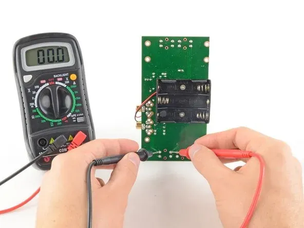
Set your multimeter to DC voltage mode. Place the black probe on a ground point (often marked as GND on the PCB) and the red probe on a power pin (like VCC, often 3.3V or 5V). A reading close to the expected value confirms the power supply is working. For example, if you're testing a 5V rail and get a reading of 4.8V–5.2V, it’s within an acceptable range.
Step 4: Measure Resistance for Component Checks
Switch to resistance mode to test components like resistors. Touch the probes to the resistor leads. If the reading matches the resistor’s labeled value (e.g., 1kΩ), it’s functioning correctly. Significant deviations might indicate a faulty component.
By mastering these basics, you'll be able to use a multimeter for PCB testing with confidence. Practice on a simple circuit first to build your skills.
Related Reading: IPC TM 650 for Beginners: A Hobbyist's Guide to Basic PCB Testing
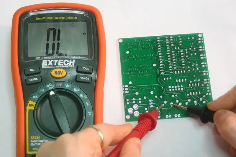
Testing Continuity on a PCB: A Key Skill
Continuity testing is one of the most useful techniques for beginners. It helps you verify if two points on a PCB are electrically connected, which is crucial for finding broken traces or bad solder joints. Here’s how to test continuity on a PCB:
Step 1: Set Up Your Multimeter
Turn the multimeter dial to continuity mode, often marked with a speaker icon. When you touch the probes together, you should hear a beep, confirming the mode is active.
Step 2: Test Traces and Solder Joints
Place one probe on a trace or pad and the other probe on another point that should be connected. If you hear a beep, the connection is good. No beep means there’s a break, possibly due to a cracked trace or poor soldering.
Step 3: Check for Shorts
Accidentally connected traces (short circuits) can cause major issues. Test between adjacent traces or pads that shouldn’t be connected. A beep here indicates a short, which you’ll need to fix by removing excess solder or cutting unwanted connections.
Continuity testing is a quick way to debug a PCB. For instance, if a circuit isn’t working, test the connection between a microcontroller pin and a sensor. A lack of continuity might reveal the problem.
Related Reading: How to Set Up a Basic PCB Testing Lab at Home
Understanding PCB Schematics: Your Roadmap to Testing
A PCB schematic is like a map of your circuit. It shows how components are connected and where signals flow. For beginners, understanding PCB schematics is essential for effective testing. Here’s how to approach it:
Step 1: Learn the Symbols
Schematics use standardized symbols. A zigzag line represents a resistor, a pair of parallel lines is a capacitor, and a triangle often indicates a diode. Familiarize yourself with these symbols using online resources or electronics textbooks.
Step 2: Follow the Connections
Lines on a schematic represent wires or traces on the PCB. Trace these lines to see how power and signals move through the circuit. For example, follow the path from a power input to a microcontroller to understand where to test for voltage.
Step 3: Identify Test Points
Schematics often label key points like VCC (power), GND (ground), or specific signal lines. Use these labels to guide your multimeter probes during testing. If a schematic shows a 3.3V line to a sensor, test that point to confirm the voltage.
By studying the schematic before testing, you’ll know exactly where to look for issues. Start with simple circuits to build your confidence in reading these diagrams.
Identifying Common PCB Problems: What to Watch For
Even with careful design and assembly, PCBs can develop issues. Identifying common PCB problems early can save your project. Here are the most frequent issues beginners encounter and how to spot them:
1. Open Circuits
An open circuit occurs when a trace or connection is broken, stopping current flow. Use continuity testing to find breaks. If a trace from a power pin to a component shows no continuity, inspect for visible cracks or poor soldering. Fixing this might involve re-soldering or adding a jumper wire.
2. Short Circuits
Shorts happen when two points that shouldn’t be connected touch, often due to excess solder or misplaced components. Use continuity mode to check for unexpected connections. If you find a short, carefully remove the excess material with a soldering iron or desoldering tool.
3. Incorrect Component Values
Using a resistor or capacitor with the wrong value can disrupt a circuit. Measure components with your multimeter before soldering them in place. For example, a 10kΩ resistor reading as 1kΩ on your multimeter is a red flag.
4. Power Supply Issues
If your PCB isn’t getting the right voltage, components won’t function. Test power rails with your multimeter. A reading far below the expected value (e.g., 2V instead of 5V) might mean a faulty power source or a damaged voltage regulator.
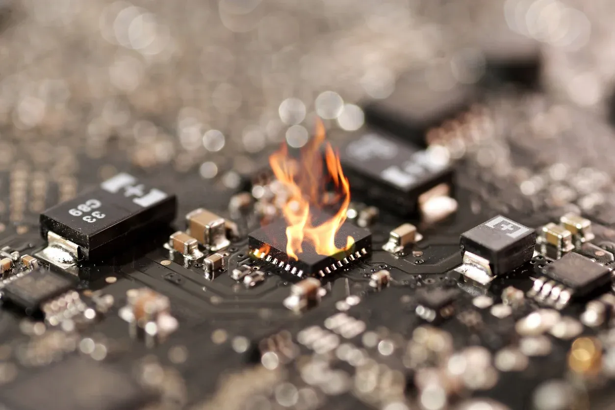
5. Damaged Components
Components like diodes or transistors can fail due to heat or overvoltage. Visually inspect for burn marks or bulging capacitors. Use your multimeter to test diodes for proper forward and reverse resistance.
By systematically checking for these issues, you can narrow down the root cause of a malfunctioning PCB. Always start with visual inspection before moving to multimeter tests.
Tips for Safe and Effective PCB Testing
As a beginner, safety and accuracy are key when testing PCBs. Follow these tips to ensure a smooth experience:
- Always work on a de-energized PCB to avoid shocks or damage.
- Use insulated probes and wear an anti-static strap to protect components.
- Double-check multimeter settings before testing to prevent incorrect measurements.
- Keep your workspace clean and organized to avoid losing small components.
- Take notes during testing to track readings and issues for future reference.
These habits will help you avoid common pitfalls and build confidence over time.
Conclusion: Building Your PCB Testing Skills
PCB test and measurement might seem daunting at first, but with the right tools and techniques, it becomes a rewarding skill. From using a multimeter for PCB testing to testing continuity on a PCB, each step helps you understand your circuit better. By mastering basic PCB testing tools, identifying common PCB problems, and understanding PCB schematics, you're well on your way to becoming a capable electronics enthusiast.
Start small with simple projects, and don’t be afraid to make mistakes—they’re part of the learning process. As you gain experience, you’ll be able to tackle more complex designs and troubleshoot with ease. Keep practicing, and soon, testing a PCB will feel like second nature.


