 ALLPCB


In the world of printed circuit board (PCB) design, breakaway tabs play a critical role in the manufacturing and depaneling process. These small, temporary connections hold multiple PCBs together during production but must break cleanly during separation without damaging the boards. How can designers ensure that breakaway tabs perform as intended? The answer lies in simulation. By using tools like PCB simulation for breakaway tabs and finite element analysis (FEA) for PCB depaneling, engineers can predict stress, identify potential failure points, and optimize designs before production begins. In this blog, we’ll dive deep into the importance of simulation in breakaway tab design, exploring how it helps in predicting stress during PCB separation and validating overall performance.
Why Breakaway Tabs Matter in PCB Manufacturing
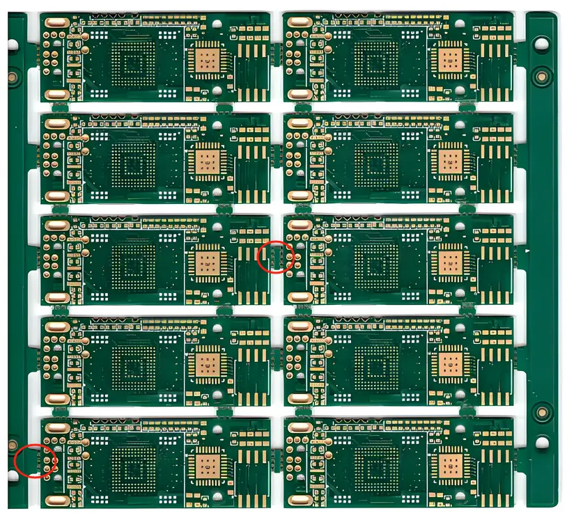
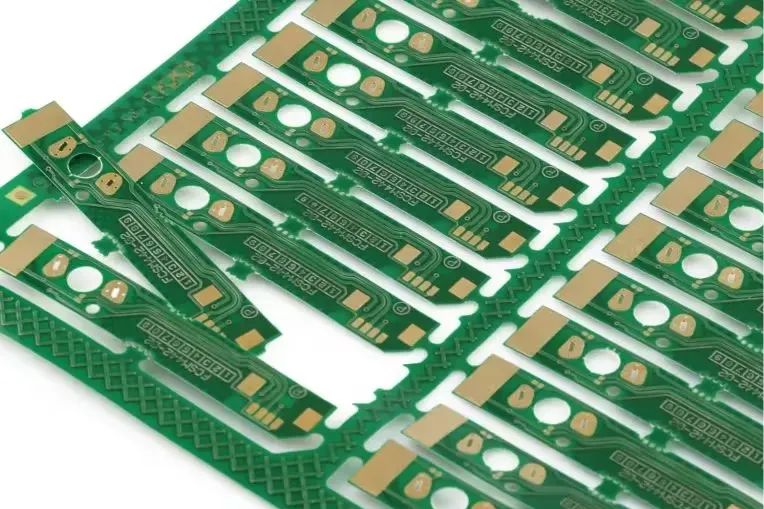
Breakaway tabs, also known as mouse bites or perforated tabs, are small sections of material that connect individual PCBs in a panel during manufacturing. These tabs make it easier to handle multiple boards as a single unit through assembly processes like soldering and testing. Once assembly is complete, the tabs are broken or cut to separate the boards into individual units—a process called depaneling.
However, poorly designed breakaway tabs can lead to issues like uneven stress distribution, cracks in the PCB substrate, or damage to nearby components during separation. This is where simulation becomes a game-changer. By simulating breakaway tab performance, engineers can foresee these problems and refine their designs to ensure clean separation and minimal risk of failure.
Understanding Stress and Failure in Breakaway Tab Design
During the depaneling process, breakaway tabs are subjected to mechanical stress as they are bent, twisted, or cut to separate the boards. If the tabs are too strong, they may require excessive force to break, risking damage to the PCB or components. If they are too weak, they might fail prematurely during handling, causing production delays.
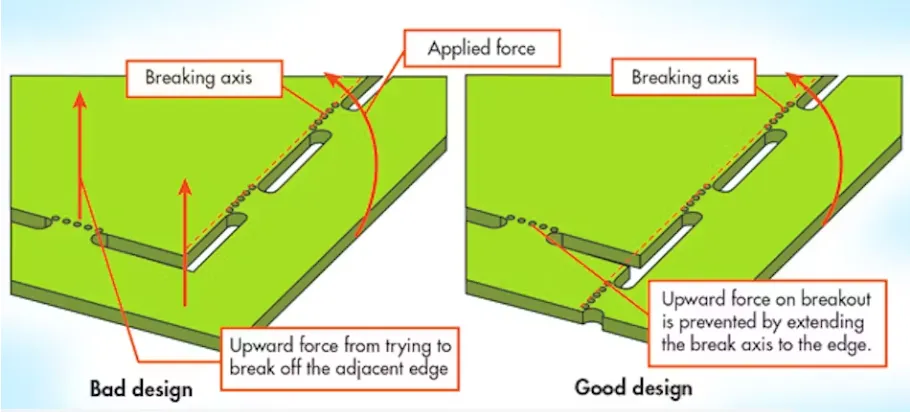
The key challenge is balancing the strength of the tabs. They need to hold the panel together securely during manufacturing but break cleanly during depaneling. Predicting stress in PCB separation is crucial to achieving this balance. Stress points often concentrate around the perforations or holes in the tabs, where the material is thinnest. If these areas are not designed properly, cracks can propagate beyond the tab and into the main board, compromising its integrity.
For instance, a typical breakaway tab might consist of small holes drilled along the separation line, leaving thin bridges of material (often 0.5 mm to 1 mm wide) that can be snapped. If the spacing between holes is too close, the bridges may fail under minimal force. If too far apart, the force required to break them could exceed safe limits, potentially causing delamination of the PCB layers.
The Power of Simulation in Breakaway Tab Design
Simulation offers a way to test breakaway tab designs virtually before any physical prototypes are made. By using software tools for PCB simulation of breakaway tabs, engineers can model how the tabs will behave under various conditions. This process involves creating a digital representation of the PCB panel, including the tabs, and applying simulated forces to mimic the depaneling process.
One of the most effective methods for this is finite element analysis (FEA). FEA analysis for PCB depaneling breaks down the design into tiny elements and calculates how stress and strain distribute across each one. This allows engineers to identify high-stress areas in the tabs and surrounding board material. For example, FEA might reveal that a tab design with 0.8 mm bridges experiences peak stress of 50 MPa at the perforation edges during separation, which could exceed the material’s yield strength of 40 MPa and lead to failure. Armed with this data, designers can adjust the tab geometry—perhaps increasing bridge width to 1.2 mm—to reduce stress below the critical threshold.
How Simulation Helps in Predicting Stress During PCB Separation
Predicting stress in PCB separation is not just about avoiding cracks or damage—it’s also about ensuring consistency across large production runs. Even small variations in material properties or manufacturing tolerances can affect how tabs perform. Simulation helps account for these variables by allowing engineers to test multiple scenarios.
For instance, a PCB made from FR-4 material typically has a tensile strength of around 310 MPa. In a simulation, engineers can apply forces ranging from 10 N to 50 N to the breakaway tabs to see how stress distributes at different load levels. If the simulation shows that stress exceeds 300 MPa near the tab edges under a 40 N load, it’s a clear sign that the design needs adjustment. Engineers might then reduce the number of perforations or increase the tab’s thickness to distribute stress more evenly.
Simulation also helps in understanding dynamic effects, such as vibrations or sudden impacts during depaneling. Tools like Ansys or similar platforms can model these conditions, showing how a sudden force of 20 N applied over 0.1 seconds might cause localized stress spikes of 400 MPa, far exceeding safe limits. By identifying these risks early, designers can reinforce critical areas or adjust the depaneling method to minimize impact.
Simulating Breakaway Tab Performance for Optimal Design
Simulating breakaway tab performance goes beyond stress analysis. It also involves evaluating how the tabs behave under real-world conditions, such as manual snapping or automated depaneling with a router or shear. Each method applies different types of forces—bending, shear, or tensile—and simulation can replicate these to ensure the tabs perform consistently.
For example, in manual depaneling, a worker might apply a bending force of 15 N over a few seconds to snap the tabs. A simulation can model this by applying a gradual load to the tab and measuring the displacement and stress at each stage. If the tab fails at 10 N instead of the expected 15 N, the design might be too weak for manual handling. On the other hand, if it requires 25 N to break, it could be too strong, risking damage to the board. Adjusting the tab’s perforation pattern—perhaps changing hole diameters from 1 mm to 1.5 mm—can fine-tune its breaking point to the desired range.
Automated depaneling introduces additional variables, such as the speed and angle of the cutting tool. Simulation can model a router moving at 100 mm/s along the tab line, calculating the shear stress (often around 200 MPa for FR-4) and ensuring it doesn’t exceed the material’s limits. This level of detail helps in creating designs that work seamlessly with specific depaneling equipment.
PCB Design Validation Through Simulation
Simulation isn’t just about designing breakaway tabs—it’s also a critical part of PCB design validation. Before sending a design to production, engineers must confirm that every element, including the tabs, meets performance and reliability standards. Validation through simulation saves time and cost by reducing the need for multiple physical prototypes.
During validation, engineers can test the entire panel under simulated manufacturing and depaneling conditions. This might include thermal stress from soldering (temperatures up to 260°C for 10 seconds) followed by mechanical stress from separation. If the simulation shows that thermal expansion causes a 0.1 mm shift in tab alignment, increasing stress by 20%, designers can adjust the tab placement or material to mitigate this effect.
Validation also ensures compliance with industry standards, such as IPC-2221, which provides guidelines for PCB design and manufacturing. By simulating how breakaway tabs respond to specified loads and conditions, engineers can confirm that their designs meet these standards, reducing the risk of costly rework or production failures.
Benefits of Using Simulation for Breakaway Tab Design
Incorporating simulation into breakaway tab design offers several key benefits:
- Reduced Risk of Failure: By predicting stress and failure points, simulation prevents costly damage during depaneling.
- Cost Savings: Virtual testing eliminates the need for multiple physical prototypes, saving time and resources.
- Improved Consistency: Simulation accounts for manufacturing variables, ensuring tabs perform reliably across large batches.
- Faster Design Cycles: Engineers can iterate designs quickly in a virtual environment, speeding up the development process.
- Enhanced Product Quality: Optimized breakaway tabs lead to cleaner separation and higher-quality finished PCBs.
Practical Tips for Implementing Simulation in Your Workflow
If you’re new to using simulation for breakaway tab design, here are some practical steps to get started:
- Choose the Right Software: Select a simulation tool with FEA capabilities and support for PCB materials. Look for platforms that allow customization of material properties and load conditions.
- Define Material Properties: Input accurate data for your PCB material, such as tensile strength (e.g., 310 MPa for FR-4) and Young’s modulus (around 22 GPa), to ensure realistic results.
- Model Realistic Conditions: Simulate the specific forces and methods used in your depaneling process, whether manual or automated.
- Iterate Based on Results: Use simulation data to refine tab geometry, perforation size, and spacing until stress levels fall within safe limits.
- Validate with Prototypes: While simulation reduces the need for prototypes, testing a final design physically can confirm the accuracy of your virtual models.
Conclusion
Breakaway tabs may seem like a small detail in PCB manufacturing, but their design can make or break the success of a production run. Through PCB simulation for breakaway tabs, FEA analysis for PCB depaneling, and predicting stress in PCB separation, engineers can create designs that balance strength and ease of separation. Simulating breakaway tab performance and validating designs virtually not only reduces the risk of failure but also saves time, cuts costs, and improves product quality. By integrating simulation into your design process, you can ensure that your PCBs separate cleanly and reliably, meeting the demands of modern manufacturing. Whether you’re handling small batches or large-scale production, the power of simulation is an essential tool for mastering breakaway tab design.


