 ALLPCB


Introduction
In the world of printed circuit board (PCB) design, every layer matters. Whether you're crafting a simple single-sided board or a complex multilayer masterpiece, the materials you choose—specifically prepreg and core—play a pivotal role in determining performance, reliability, and manufacturability. For engineers, understanding the difference between prepreg and core isn't just a technical detail; it's the foundation of creating PCBs that meet stringent electrical, thermal, and mechanical demands. At its core (pun intended), this blog dives into these two essential PCB stackup materials, breaking down their roles, properties, and how they shape your design outcomes. Let's explore what makes prepreg and core distinct, why they matter, and how to leverage them effectively in your next project.
Why does this topic deserve your attention? As devices shrink and performance expectations soar—think 5G, IoT, or high-speed computing—the stakes for getting your PCB stackup right have never been higher. A misstep in material selection could mean signal loss, impedance mismatches, or even board failure. Stick with us as we unpack these critical components with practical insights and real-world examples.
What Are Prepreg and Core in PCB Design?
Defining the Basics
To kick things off, let's define our players. Prepreg, short for 'pre-impregnated,' is a dielectric material made of fiberglass or another woven fabric soaked with a resin (usually epoxy) that's partially cured—often referred to as 'B-stage.' This semi-cured state makes prepreg pliable, allowing it to act as the glue that binds layers together during PCB lamination. When heated and pressed, the resin flows, bonds to adjacent layers, and fully cures, creating a solid, insulating structure.
Core, on the other hand, is the rigid backbone of a PCB. It's a fully cured laminate—typically FR4, a fiberglass-epoxy composite—clad with copper foil on one or both sides. Core provides the structural stability and serves as the base for etched circuitry. In a multilayer PCB, cores are the pre-fabricated building blocks, while prepreg fills the gaps between them.
Recommend Reading: Core Thickness Matters: How PCB Substrate Affects Signal Integrity and Performance
Key Differences at a Glance
While both prepreg and core often start with similar materials (fiberglass and epoxy), their roles and states set them apart:
- State: Core is fully cured and rigid; prepreg is semi-cured and flexible until lamination.
- Function: Core hosts copper traces and provides rigidity; prepreg insulates and bonds layers.
- Copper: Core comes with copper pre-laminated; prepreg does not.
Understanding these distinctions is the first step to mastering PCB stackup design. Let's dig deeper into their properties and applications.
The Role of Prepreg in PCB Stackups
Binding and Insulating
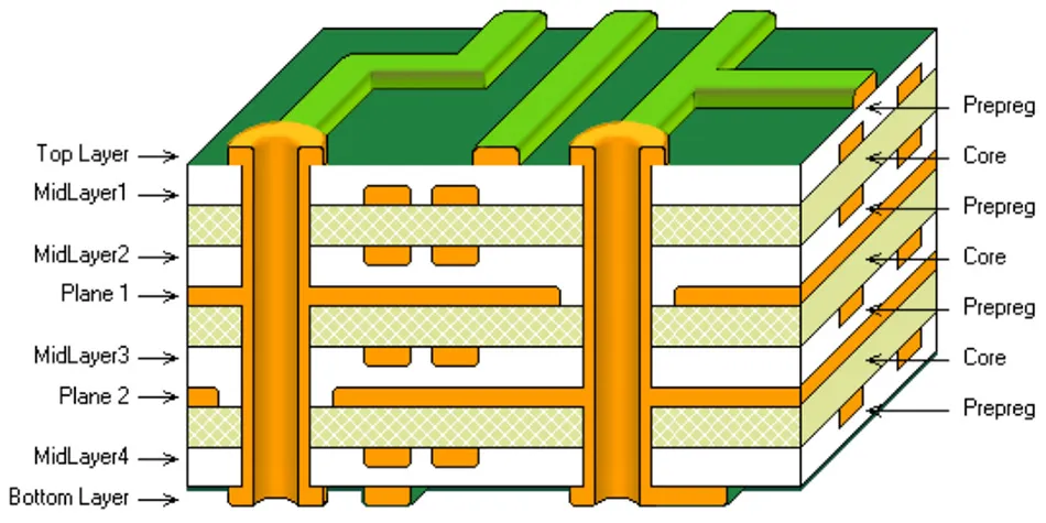
Prepreg's starring role is as the adhesive that holds a multilayer PCB together. Imagine stacking several cores—each with etched copper traces—and needing a way to fuse them into a single, cohesive unit. That's where prepreg steps in. During lamination, heat and pressure cause the resin to flow, filling gaps and bonding to the copper and core surfaces. Once cured, it becomes a robust dielectric layer, electrically isolating the conductive layers while contributing to the board's overall thickness.
For example, in a 4-layer PCB using foil construction, prepreg sits between layers 1 and 2, and layers 3 and 4, sandwiching a central core. This setup ensures insulation while maintaining structural integrity.
Types of Prepreg
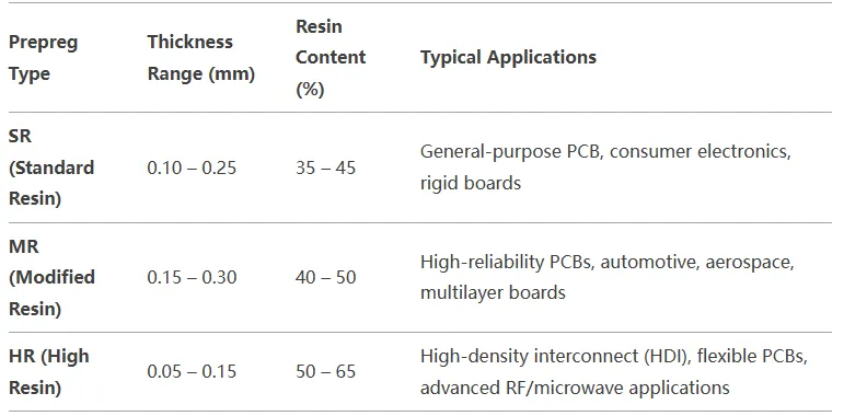
Not all prepregs are created equal. They vary based on resin content and glass weave, impacting their thickness and electrical properties:
- Standard Resin (SR): Lower resin content, thinner profile—ideal for basic applications.
- Medium Resin (MR): Balanced resin for moderate thickness and insulation needs.
- High Resin (HR): Higher resin content for thicker layers or better flow in complex stackups.
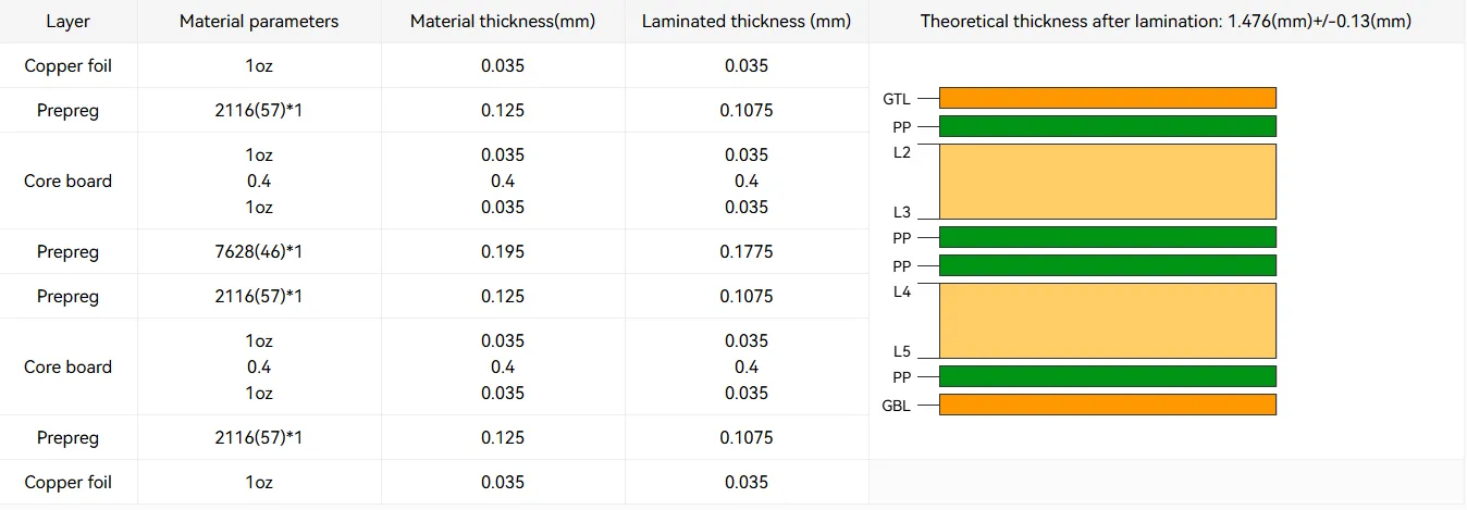
The glass weave—denoted by numbers like 106, 1080, or 7628—also matters. A tighter weave (e.g., 7628) offers higher density and strength, while a looser weave (e.g., 1080) is thinner and more flexible. For a high-frequency design targeting 50-ohm impedance, a 2116 prepreg (medium thickness) might be paired with a core to achieve precise dielectric spacing.
Practical Impact
Prepreg's thickness and dielectric constant (Dk) directly affect signal integrity. A typical FR4 prepreg has a Dk of around 4.2–4.5, but this can vary post-lamination due to resin flow and glass content. In high-speed designs, inconsistent prepreg thickness can skew impedance, leading to signal reflections. Engineers often specify multiple prepreg plies (e.g., two sheets of 1080 at 0.0028 inches each) to hit a target thickness like 0.006 inches, balancing cost and performance.
Suggested Reading: Prepreg Thickness & Dielectric Constant: Optimizing PCB Performance
The Role of Core in PCB Stackups
Structural Foundation
If prepreg is the glue, core is the skeleton. It's the pre-laminated, copper-clad material that forms the base layers of a PCB. In a single-sided board, the core might be the only layer, with copper etched on one side. In multilayer designs, cores stack up, hosting the inner signal, ground, or power planes. For instance, a 6-layer PCB might use two cores (layers 2-3 and 4-5) with prepreg and foil on the outer layers.
Core thickness varies widely—common options include 0.005 inches (0.127 mm) to 0.062 inches (1.6 mm)—and copper weight ranges from 0.5 oz (17.5 µm) to 2 oz (70 µm) or more, depending on current-carrying needs.
Further Reading: The Impact of Prepreg Thickness on PCB Impedance Control: A Deep Dive
Electrical Stability
Unlike prepreg, core's fully cured state gives it consistent dielectric properties, making it a go-to for controlled impedance layers. A core with a Dk of 4.3 and a thickness of 0.010 inches might be used between a signal layer and ground plane to maintain a 50-ohm trace impedance, calculated using tools like a field solver. This predictability is why high-frequency designs often place critical signals on core layers rather than relying solely on prepreg.
Real-World Example
Consider a DDR4 memory board operating at 3200 MT/s. The stackup might use a 0.008-inch core between layers 3 and 4 to ensure stable impedance for high-speed signals, with prepreg filling the gaps to outer layers. This setup minimizes signal loss (dissipation factor ~0.02 for FR4 core) compared to a prepreg-only approach.
Prepreg vs. Core: A Side-by-Side Comparison
Material Properties
Let's break it down:
- Rigidity: Core is stiff; prepreg starts flexible and hardens post-lamination.
- Dielectric Constant: Core's Dk is stable (e.g., 4.3); prepreg's varies slightly (4.2–4.5) due to curing.
- Thickness Control: Core offers precise, pre-set thicknesses; prepreg's final thickness depends on lamination pressure and resin flow.
Manufacturing Implications
In fabrication, cores are etched individually before stacking, while prepreg is added during lamination. Foil construction—using prepreg between cores and outer copper foil—is standard for its cost-effectiveness and yield. Cap construction, with cores on the outside, suits niche cases like microwave boards needing tighter Dk control but adds complexity.
Performance Considerations
For signal integrity, core wins in high-frequency scenarios due to its lower dissipation factor and uniform Dk. Prepreg, however, excels at filling gaps and adapting to uneven surfaces, crucial for dense multilayer boards. A 10-layer PCB might alternate three cores and four prepreg layers to balance rigidity and insulation.
How Prepreg and Core Affect Signal Integrity
Impedance Control
Impedance is king in high-speed designs. A 50-ohm microstrip on a 0.010-inch core (Dk 4.3) requires a trace width of about 0.018 inches, per standard calculators. Swap that for a prepreg layer with a variable Dk (say, 4.5 after curing), and the width shifts, risking mismatches. Core's consistency makes it the preferred choice for critical paths.
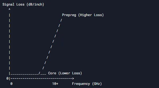
Signal Loss and Crosstalk
At 5 GHz, FR4 core's dissipation factor (~0.02) keeps signal loss low, while prepreg's slightly higher loss tangent (~0.025) can degrade performance over long traces. Thinner prepreg layers also reduce crosstalk by spacing signal layers closer to ground planes—e.g., a 0.004-inch prepreg cuts coupling compared to 0.008 inches.
Practical Design Tip
For a USB 3.0 board (5 Gbps), use a core for the differential pair (90-ohm impedance) and prepreg to isolate it from power planes. Test coupons—mini PCBs with identical stackups—can validate real-world Dk and loss values.
Choosing Between Prepreg and Core for Your Stackup
Design Requirements
Your project dictates the mix:
- High-Speed: Favor cores for signal layers; use prepreg for bonding.
- Thick Boards: Stack multiple cores with prepreg to hit targets like 0.093 inches.
- Cost: Foil construction with fewer cores saves money over cap builds.
Material Selection
FR4 dominates, but alternatives like Rogers 4350 (Dk 3.5, low loss) suit RF designs. A 10 GHz antenna might pair a Rogers core with FR4 prepreg for cost-effective insulation. Check supplier datasheets—e.g., Isola's 370HR offers a Dk of 4.0 and thermal stability up to 180°C.
Collaboration with Fabricators
Don't guess—talk to your fab house. Specify impedance (e.g., 100 ohms differential) and thickness (e.g., 1.6 mm), and let them suggest a stackup. A 6-layer board might use two 0.020-inch cores and 0.006-inch prepreg layers, adjusted for in-stock materials.
Common Stackup Configurations
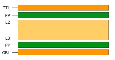
4-Layer PCB
- Foil Build: Copper foil, prepreg, core (layers 2-3), prepreg, copper foil.
- Use Case: General-purpose boards like Arduino shields.
Click Introduction to 4 Layer PCB to get a more comprehensive understanding of 4-layer PCB.
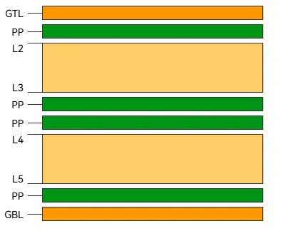
6-Layer PCB
- Foil Build: Foil, prepreg, core (2-3), prepreg, core (4-5), prepreg, foil.
- Use Case: High-speed digital with ground planes.
Click 6 Layer PCB - Stackup & Prototype to get a more comprehensive understanding of 6-layer PCB.
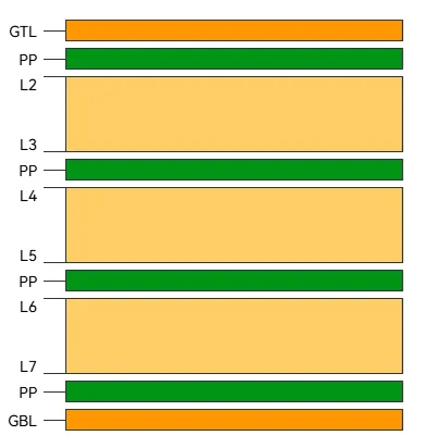
8-Layer PCB
- Foil Build: Foil, prepreg, core (2-3), prepreg, core (4-5), prepreg, core (6-7), prepreg, foil.
- Use Case: Servers or telecom equipment.
Click What is 8 Layer PCB to get a more comprehensive understanding of 8-layer PCB.
Challenges and Solutions in Using Prepreg and Core
Thickness Variability
Prepreg's final thickness can shift ±10% due to resin flow. Solution: Use multiple thin plies (e.g., three 106 sheets) for precision over one thick 7628 sheet.
Thermal Stress
High-layer-count boards risk delamination. Opt for high-Tg materials (e.g., FR4 with Tg 170°C) and symmetrical stackups to evenly distribute stress.
Cost vs. Performance
Exotic cores like Rogers spike costs. Balance with FR4 prepreg where performance allows, reserving specialty materials for critical layers.
How ALLPCB Supports Your Stackup Needs
For engineers navigating the complexities of prepreg and core selection, partnering with a reliable manufacturer is key. ALLPCB offers quick-turn prototyping to test stackup designs—think 24-hour turnaround for a 4-layer board—plus advanced manufacturing capabilities for multilayer PCBs up to 32 layers. Our global logistics ensure fast delivery, while our engineering team collaborates to optimize stackups for impedance, thickness, and cost. Whether you're prototyping a high-speed design or scaling production, we've got the tools and expertise to bring your vision to life.
Conclusion
Prepreg and core are the unsung heroes of PCB stackups, each bringing unique strengths to the table. Core provides the rigid, stable base for circuitry, while prepreg binds it all together, ensuring insulation and flexibility in design. For engineers, mastering their interplay means unlocking better signal integrity, thermal performance, and manufacturability. Whether you're chasing 50-ohm impedance for a 5G module or building a budget-friendly IoT sensor, the right mix of these materials is your ticket to success. Next time you design a PCB, consider your stackup carefully—because in this game, every layer counts.


