ALLPCB


When it comes to PCB assembly, understanding the differences in functional testing between Through-Hole Technology (THT) and Surface Mount Technology (SMT) is crucial for engineers and manufacturers. Both methods have unique challenges and testing approaches that impact the reliability and performance of electronic devices. In this comprehensive guide, we’ll explore the functional test challenges for Through-Hole and Surface Mount Technology, compare SMT functional test methods, and provide actionable insights to help you ensure quality in your PCB designs.
Whether you're dealing with Through-Hole functional test challenges or seeking effective Surface Mount Technology test strategies, this blog will break down the essentials. Let’s dive into the specifics of testing these two dominant PCB assembly techniques and uncover the best practices for achieving optimal results.
What Are Through-Hole Technology and Surface Mount Technology?
Before we delve into functional testing, it’s important to understand the basics of the two primary PCB assembly methods. Through-Hole Technology (THT) involves inserting component leads through holes drilled in the PCB and soldering them on the opposite side. This method has been a staple in electronics for decades due to its durability and ease of manual assembly. On the other hand, Surface Mount Technology (SMT) involves mounting components directly onto the surface of the PCB, allowing for smaller, more compact designs and automated assembly processes.
Both techniques serve different purposes depending on the application. THT is often used in high-power or high-reliability applications, such as power supplies or industrial equipment, while SMT dominates in consumer electronics due to its space efficiency and suitability for high-density designs. However, the differences in assembly also lead to unique challenges when it comes to functional testing, which we’ll explore in detail.

Functional Testing: Why It Matters for PCB Assembly
Functional testing is a critical step in the PCB manufacturing process. It verifies that the assembled board performs as intended under real-world conditions. This type of testing goes beyond visual inspection or basic electrical checks, focusing on the overall operation of the circuit, including signal integrity, power distribution, and component interaction. For both THT and SMT, functional testing ensures that the final product meets design specifications and reliability standards.
However, the testing process for each technology varies significantly due to differences in component placement, soldering techniques, and board layouts. Let’s break down the specific challenges and methods for functional testing in Through-Hole and Surface Mount assemblies.
Through-Hole Functional Test Challenges
Through-Hole Technology, while robust and reliable, presents several challenges during functional testing. These challenges stem from the physical nature of the components and the assembly process. Below are some of the key issues engineers face when testing THT boards:
- Component Accessibility: Since THT components are soldered through holes and often have leads on the opposite side of the board, accessing test points can be difficult. This can complicate in-circuit testing (ICT), where probes need to make contact with specific nodes. For instance, a typical THT board may have components with leads spaced at 2.54 mm (0.1 inches), requiring precise test fixtures to avoid misalignment.
- Solder Joint Reliability: THT relies heavily on manual or wave soldering, which can lead to inconsistent solder joints. Issues like cold solder joints or excess solder can cause intermittent connections, making functional testing more complex. Testing may reveal failures under thermal stress, where a poor joint might crack at temperatures above 85°C.
- Signal Integrity in High-Speed Designs: THT components, due to their longer leads, can introduce parasitic inductance and capacitance, affecting signal integrity in high-speed applications. For example, a lead length of 10 mm can add up to 10 nH of inductance, causing signal delays or noise. Functional tests must account for these effects, often requiring specialized equipment to measure impedance and signal response.
- Mechanical Stress Testing: THT components are often used in applications subject to vibration or mechanical stress, such as automotive or industrial systems. Functional testing must simulate these conditions to ensure components remain secure. A typical test might involve subjecting the board to vibrations at 10-55 Hz to check for lead fatigue or solder joint failure.
Addressing these Through-Hole functional test challenges requires a combination of precise test fixtures, environmental stress testing, and thorough inspection of solder joints. Engineers often use automated test equipment (ATE) with custom bed-of-nails fixtures to ensure reliable contact with test points, even on densely populated THT boards.

SMT Functional Test: Challenges and Considerations
Surface Mount Technology testing, while benefiting from automation and compact designs, comes with its own set of challenges. SMT functional test methods must account for the smaller size of components, higher densities, and advanced soldering techniques. Here are the primary challenges in SMT functional testing:
- Small Component Size and Density: SMT components, such as 0402 resistors or QFN packages, are incredibly small, often measuring less than 1 mm in width. This makes it difficult to place test probes accurately during in-circuit testing. High-density boards may have components spaced less than 0.5 mm apart, increasing the risk of probe misalignment or short circuits during testing.
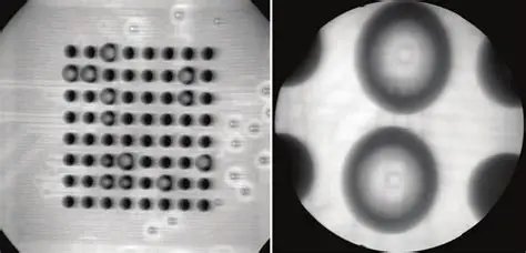
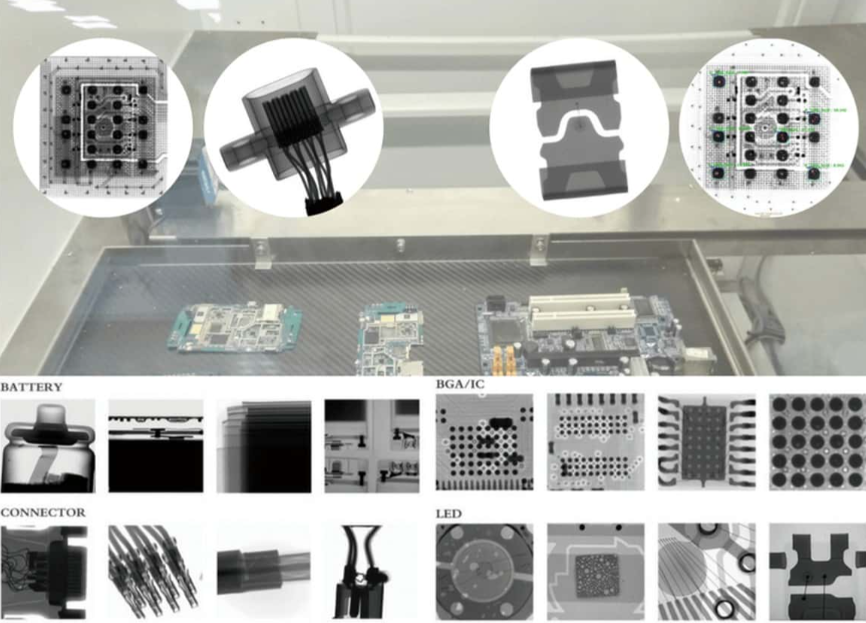
- Solder Joint Inspection: SMT components are soldered using reflow processes, which can result in hidden defects like insufficient solder paste or tombstoning (where a component lifts on one side). Functional testing must be paired with techniques like Automated Optical Inspection (AOI) or X-ray imaging to detect these issues. For instance, X-ray testing can reveal voids in BGA (Ball Grid Array) solder joints, which might cause failures under thermal cycling between -40°C and 125°C.
- Thermal and Power Management: SMT boards often power high-performance devices, leading to significant heat dissipation challenges. Functional testing must verify that the board operates within thermal limits, often using thermal imaging to identify hot spots. A typical SMT board might fail if a component exceeds 100°C during operation, indicating a design or soldering flaw.
- Signal Integrity at High Frequencies: SMT designs are common in high-speed electronics, where signal integrity is paramount. Functional testing must measure parameters like signal rise time (often below 1 ns) and impedance mismatches (targeting 50 ohms for many RF applications). Even minor soldering defects can introduce noise or crosstalk, requiring advanced test setups with oscilloscopes or vector network analyzers.
To tackle these SMT functional test challenges, manufacturers often rely on a combination of AOI, X-ray inspection, and automated functional test systems. These methods ensure that even the smallest defects are identified before the board reaches the end user.
Testing Methods: THT vs. SMT Comparison
While both THT and SMT aim to ensure PCB reliability through functional testing, the methods and tools used differ significantly. Below is a detailed comparison of the testing approaches for each technology, focusing on practical applications and effectiveness.
1. In-Circuit Testing (ICT)
For THT, ICT is a common method that uses a bed-of-nails fixture to contact test points on the board. This approach works well for larger components with accessible leads but can be time-consuming to set up for complex boards. In contrast, SMT boards often require flying probe testers for ICT due to their high density and smaller test points. Flying probe systems use movable probes to access tiny pads, offering flexibility but slower test speeds compared to bed-of-nails setups. For example, a flying probe test on an SMT board might take 2-3 minutes per board, while a THT bed-of-nails test could complete in under 30 seconds for simpler designs.
2. Automated Optical Inspection (AOI)
AOI is more critical for SMT due to the small size of components and the risk of placement errors. High-resolution cameras can detect issues like misaligned components or insufficient solder with accuracy down to 0.01 mm. For THT, AOI is less common since components are larger and defects are often visible to the naked eye. However, when used, AOI for THT focuses on solder joint quality on the underside of the board.
3. X-Ray Inspection
X-ray testing is almost exclusively used for SMT, especially for components like BGAs where solder joints are hidden under the package. This method can detect voids or cracks with precision, ensuring reliability in high-stakes applications. THT rarely requires X-ray inspection since solder joints are visible and accessible for manual or visual checks.
4. Environmental Stress Testing
Both THT and SMT boards undergo environmental testing to simulate real-world conditions. However, THT testing often focuses on mechanical stress, such as vibration or shock, due to its use in rugged applications. SMT testing prioritizes thermal cycling and humidity tests to ensure reliability in compact, heat-intensive designs. For instance, an SMT board might be tested across a temperature range of -40°C to 85°C to mimic consumer device conditions.
5. Functional Test Equipment
Functional testing for both technologies often involves custom ATE systems, but the complexity differs. THT boards may require simpler setups to test basic analog and digital functions, while SMT boards often need advanced equipment to measure high-frequency signals or power efficiency. A typical SMT functional test might involve checking a microcontroller’s response time at 100 MHz, requiring precise oscilloscopes and signal generators.

Best Practices for Functional Testing in THT and SMT
To achieve reliable results in functional testing for both Through-Hole and Surface Mount Technology, consider the following best practices tailored to each method:
- For THT: Invest in robust test fixtures to ensure consistent contact with test points. Regularly inspect solder joints for cracks or cold joints, especially in high-stress applications. Use environmental stress testing to simulate vibration and thermal conditions common in industrial settings.
- For SMT: Combine AOI and X-ray inspection to catch hidden defects early in the process. Use flying probe testers for high-density boards and prioritize thermal testing to address heat dissipation issues. Ensure test equipment can handle high-speed signals for modern electronics.
- For Both: Develop a comprehensive test plan that includes functional, environmental, and stress testing. Automate as much of the process as possible to reduce human error and increase throughput. Document test results meticulously to identify patterns or recurring issues in assembly.
Conclusion: Choosing the Right Testing Strategy for Your PCB
Functional testing for Through-Hole Technology and Surface Mount Technology is essential to ensure the reliability and performance of electronic devices. While THT presents challenges related to component accessibility and mechanical stress, SMT requires advanced techniques to address small component sizes and high-density designs. By understanding the unique Through-Hole functional test challenges and mastering SMT functional test methods, engineers can develop effective Surface Mount Technology test strategies tailored to their specific needs.
At the core of successful PCB assembly is a well-designed testing process that accounts for the strengths and limitations of each technology. Whether you’re working on a rugged industrial system with THT or a compact consumer device with SMT, leveraging the right tools and methods will help you deliver high-quality, dependable products. With careful planning and the right approach, functional testing can bridge the gap between design and real-world performance, ensuring your boards meet the highest standards.