 ALLPCB


In the high-stakes world of aerospace, the reliability of aircraft cockpit display PCBs (Printed Circuit Boards) is non-negotiable. These critical components power navigation, communication, and monitoring systems, ensuring pilots have real-time data to make life-saving decisions. Designing PCBs for such environments demands precision, durability, and adherence to strict standards. This blog dives deep into aerospace PCB design guidelines, focusing on aircraft display PCB reliability, high-temperature PCB design, vibration resistant PCB techniques, and the role of conformal coating for PCBs. Whether you're an engineer or a designer, you'll find actionable best practices to create robust and reliable cockpit display systems.
Why High-Reliability Matters for Aircraft Cockpit Display PCBs
Aircraft cockpit displays are the heart of a pilot's interaction with the aircraft. From altitude indicators to navigation maps, these systems rely on PCBs to function flawlessly under extreme conditions. A single failure can lead to catastrophic consequences, making reliability the top priority. Aerospace PCBs must withstand high temperatures, intense vibrations, humidity, and electromagnetic interference (EMI) while maintaining signal integrity. By following proven design guidelines, you can ensure these boards perform consistently in the harshest environments.

Key Challenges in Designing Aircraft Cockpit Display PCBs
Before diving into best practices, it's important to understand the unique challenges these PCBs face. Cockpit environments expose electronics to:
- Extreme Temperatures: Temperatures can range from -40°C at high altitudes to over 85°C in certain conditions, requiring high-temperature PCB design.
- Vibrations and Shock: Constant turbulence and take-off/landing forces demand vibration resistant PCB structures.
- Humidity and Corrosion: Moisture in the air can degrade components, making protective measures like conformal coating for PCBs essential.
- EMI and Signal Integrity: With multiple electronic systems operating nearby, PCBs must resist interference to ensure clear data transmission for displays.
Addressing these challenges starts with a solid design foundation. Let’s explore the best practices for achieving high reliability in aircraft cockpit display PCBs.
Aerospace PCB Design Guidelines for Cockpit Displays
Designing PCBs for aerospace applications, especially cockpit displays, requires strict adherence to industry standards and meticulous attention to detail. Below are key aerospace PCB design guidelines to ensure reliability and performance.
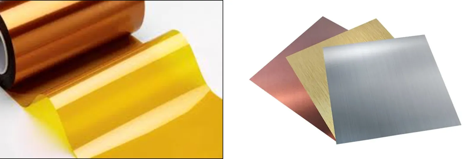
1. Choose the Right Materials for High-Temperature Environments
Material selection is critical for high-temperature PCB design. Standard FR-4 materials often fail under the thermal stress of aerospace environments. Instead, opt for high-Tg (glass transition temperature) materials like polyimide or ceramic-based substrates. These materials can handle temperatures above 150°C without deforming or losing electrical properties. For example, polyimide boards offer a Tg of up to 250°C, making them ideal for cockpit display PCBs exposed to heat from nearby equipment.
Additionally, ensure that the copper thickness (typically 1-2 oz for most layers) supports current capacity without overheating. Thermal vias can also be added to dissipate heat effectively, maintaining component longevity.
2. Design for Vibration Resistance
Aircraft experience constant vibrations, especially during take-off, landing, and turbulence. A poorly designed PCB can suffer from cracked solder joints or component detachment. To create a vibration resistant PCB, consider these strategies:
- Minimize Component Weight: Use lightweight surface-mount components to reduce stress on solder joints during vibrations.
- Secure Mounting: Design the PCB with multiple mounting points to distribute mechanical stress evenly. Use reinforced holes or brackets for added stability.
- Avoid Tall Components: Tall or heavy components are more prone to movement. If unavoidable, secure them with adhesives or mechanical fasteners.
- Flexible Design: For extreme cases, consider rigid-flex PCBs, which combine rigid and flexible sections to absorb vibrations without breaking.
Testing for vibration resistance is also critical. Standards like MIL-STD-810G specify vibration test profiles (e.g., sinusoidal vibrations at 10-2000 Hz) to simulate real-world conditions. Ensure your design passes these tests before deployment.
3. Optimize Layout for Signal Integrity
Cockpit display PCBs often handle high-speed signals for real-time data updates. Poor layout can lead to signal degradation or EMI issues. Follow these tips to maintain aircraft display PCB reliability:
- Controlled Impedance: Design traces with controlled impedance (e.g., 50 ohms for high-speed signals) to prevent signal reflection and loss.
- Ground Planes: Use solid ground planes to reduce EMI and provide a stable reference for signals.
- Trace Spacing: Maintain adequate spacing between high-speed traces (at least 3x the trace width) to avoid crosstalk.
- Shielding: Incorporate shielding layers or cans around sensitive components to block external interference.
Simulation tools can help predict signal behavior before manufacturing. Aim for signal integrity metrics like a maximum jitter of 5% of the signal period to ensure clear data transmission to displays.
4. Apply Conformal Coating for Environmental Protection
Moisture, dust, and chemical contaminants can degrade PCB performance over time. Conformal coating for PCBs acts as a protective barrier, shielding the board from environmental hazards. Common coating types for aerospace applications include:
- Silicone: Offers excellent thermal resistance (up to 200°C) and flexibility, ideal for high-temperature and vibration-prone environments.
- Parylene: Provides superior moisture resistance and a thin, uniform layer, often used in military-spec applications.
- Acrylic: Easy to apply and rework, suitable for less extreme conditions but still effective against humidity.
When applying conformal coating, ensure full coverage of sensitive areas like solder joints and connectors. However, avoid coating areas that require rework or testing access. Follow standards like IPC-CC-830 for coating application to guarantee reliability.
Thermal Management Strategies for High-Temperature PCB Design
Thermal stress is a major concern for cockpit display PCBs, as overheating can lead to component failure or signal distortion. Effective high-temperature PCB design requires robust thermal management. Here are proven strategies:
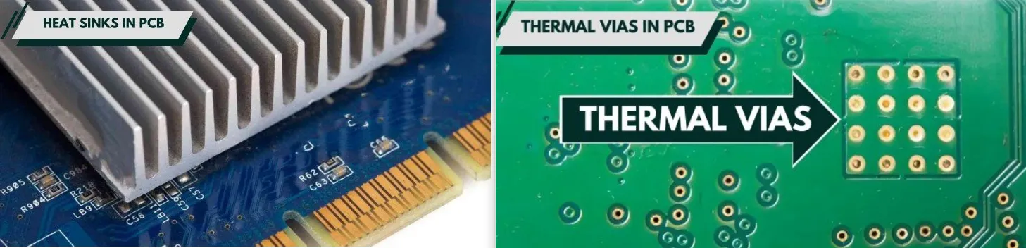
- Thermal Vias: Place thermal vias under heat-generating components like processors or power ICs to transfer heat to other layers or a heat sink. A via density of 8-10 per square inch is often recommended for high-power areas.
- Heat Sinks: Attach heat sinks or heat spreaders to critical components to dissipate heat into the surrounding environment.
- Component Placement: Position heat-sensitive components away from high-power elements. Use thermal simulation to identify hot spots during the design phase.
- Copper Pours: Increase copper thickness or add copper pours on outer layers to improve heat distribution across the board.
Testing under thermal cycling conditions (e.g., -55°C to 125°C as per IPC-TM-650) ensures the PCB can handle temperature fluctuations without cracking or delaminating.
Testing and Validation for Aircraft Display PCB Reliability
Designing a reliable PCB is only half the battle. Rigorous testing ensures it meets aerospace standards for aircraft display PCB reliability. Key tests include:
- Environmental Testing: Simulate temperature, humidity, and altitude extremes to verify performance under real-world conditions.
- Vibration and Shock Testing: Use standards like MIL-STD-810G to confirm the board’s durability against mechanical stress.
- EMI Testing: Test for electromagnetic compatibility (EMC) to ensure the PCB doesn’t interfere with other cockpit systems.
- Accelerated Life Testing (ALT): Subject the PCB to accelerated stress to predict long-term reliability and identify potential failure points.
Document all test results and iterate on the design if issues arise. Compliance with standards like DO-160 (environmental conditions for airborne equipment) is mandatory for aerospace certification.
Manufacturing Considerations for Aerospace PCBs
Even the best design can fail if manufacturing isn’t executed with precision. Partner with a manufacturer experienced in aerospace applications to ensure:
- Tight Tolerances: Aerospace PCBs often require tolerances as tight as ±0.1 mm for trace widths and spacing.
- Quality Materials: Verify that only certified, high-grade materials are used, with traceability for every batch.
- Inspection and Testing: Implement in-process inspections like Automated Optical Inspection (AOI) and X-ray for hidden defects.
Collaboration between design and manufacturing teams is essential to avoid costly rework and ensure the final product meets reliability standards.
Future Trends in Aircraft Cockpit Display PCB Design
As aerospace technology evolves, so do the demands on cockpit display PCBs. Emerging trends include:
- Miniaturization: Smaller, denser PCBs to accommodate advanced features in limited cockpit space.
- Advanced Materials: Wider adoption of graphene-based substrates for superior thermal and electrical performance.
- AI Integration: Smart PCBs with embedded AI to process data locally, reducing latency in critical systems.
Staying ahead of these trends ensures your designs remain relevant and competitive in the fast-paced aerospace industry.
Conclusion: Building Reliability into Every Layer
Designing aircraft cockpit display PCBs is a complex task that demands precision, foresight, and adherence to strict aerospace PCB design guidelines. By focusing on high-temperature PCB design, creating vibration resistant PCB structures, applying conformal coating for PCBs, and prioritizing aircraft display PCB reliability, you can build systems that perform flawlessly under the most demanding conditions. From material selection to thermal management and rigorous testing, every step plays a vital role in ensuring safety and efficiency in the skies.
At ALLPCB, we’re committed to supporting engineers and designers with the tools and expertise needed to bring reliable aerospace solutions to life. By following these best practices, you can confidently design PCBs that meet the rigorous demands of modern aircraft cockpits.


