 ALLPCB


If you're looking to perfect the SMT process for flexible PCBs, you've come to the right place. Surface Mount Technology (SMT) assembly on flexible boards can be tricky due to their unique properties, but with the right techniques and best practices, you can achieve reliable and high-quality results. In this comprehensive guide, we'll dive into the key aspects of SMT assembly on flex boards, covering everything from pick and place challenges to reflow soldering profiles, stencil design, and automated optical inspection (AOI). Let's explore how to master this process step by step.
Understanding the SMT Process for Flexible PCBs
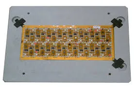
Flexible printed circuit boards (PCBs) are increasingly popular in industries like wearables, medical devices, and automotive electronics due to their ability to bend and conform to unique shapes. However, the SMT process for flexible PCBs comes with distinct challenges compared to rigid boards. The thin, pliable material can warp or bend during assembly, which may lead to misaligned components or weak solder joints.
The SMT process for flexible PCBs starts with careful preparation. Before assembly begins, the flex board must be secured properly to prevent movement or deformation. Often, PCB manufacturers use custom fixtures or carriers to hold the board flat during the process. This ensures precision during component placement and soldering. Additionally, the material's sensitivity to heat requires tailored approaches to soldering and inspection, which we'll cover in detail below.
Pick and Place Challenges on Flex Boards
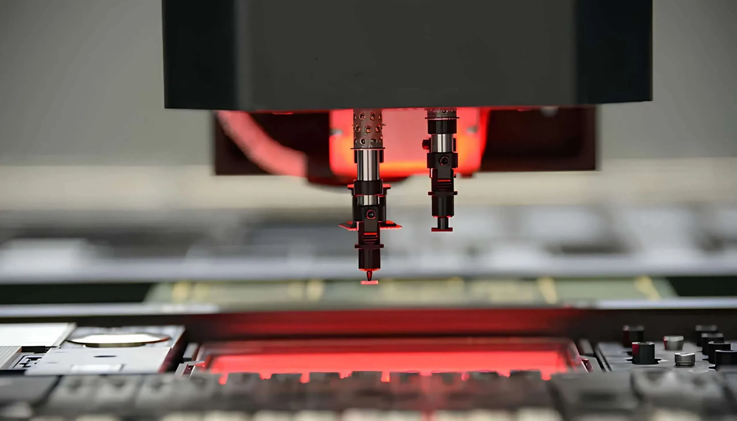
One of the biggest hurdles in SMT assembly for flexible PCBs is the pick and place process. Unlike rigid PCBs, flex boards can shift or deform under the pressure of pick and place machines, leading to inaccurate component placement. Here are some key challenges and best practices to overcome them:
- Board Stability: As mentioned, flex boards need to be held securely. Using a rigid carrier or vacuum table can help maintain stability during component placement. This reduces the risk of the board bending under the machine's nozzle pressure.
- Component Alignment: Flex boards often have smaller pad sizes due to space constraints. This requires high-precision pick and place machines with vision systems to ensure components are aligned correctly. A misalignment as small as 0.1 mm can cause connection issues.
- Nozzle Selection: The nozzles used in pick and place machines must be chosen carefully. Softer or customized nozzles can prevent damage to the flexible material while still providing a secure grip on components.
By addressing these pick and place challenges on flex boards, manufacturers can achieve higher accuracy and reduce rework. Investing in advanced equipment with adjustable pressure settings and vision alignment systems is often worth the cost for consistent results.
Reflow Soldering Profiles for Flex PCBs
Reflow soldering is a critical step in SMT assembly, and creating the right reflow soldering profiles for flex PCBs is essential to avoid damaging the delicate material. Flexible boards are typically made of polyimide or similar materials that have lower heat resistance compared to rigid FR4 boards. Excessive heat can cause warping, delamination, or even burning of the substrate.
To develop an effective reflow soldering profile for flex PCBs, consider the following:
- Lower Peak Temperatures: Unlike rigid boards, which can handle peak temperatures of 245-260°C, flex boards often require peak temperatures between 220-235°C. This minimizes thermal stress on the material.
- Gradual Ramp-Up: A slower ramp-up rate (1-2°C per second) helps prevent thermal shock. Sudden temperature changes can cause the board to warp or components to shift.
- Shorter Soak Time: Limit the time spent in the soak zone (typically 150-180°C) to 60-90 seconds. This reduces prolonged heat exposure while ensuring the solder paste activates properly.
- Cooling Rate: A controlled cooling rate of 2-4°C per second prevents internal stresses in the board and solder joints, which could lead to cracks or failures.
Testing and optimizing the reflow profile is crucial. Many manufacturers use thermal profiling tools to monitor the temperature across different zones of the board during soldering. This data helps fine-tune the oven settings for consistent results. For example, a well-optimized profile can reduce defect rates by up to 30%, ensuring stronger solder joints and better reliability.

Stencil Design for Flexible PCB Assembly
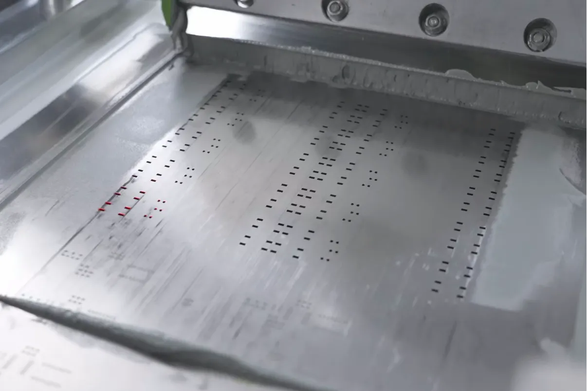
Stencil design for flexible PCB assembly plays a vital role in ensuring proper solder paste application. Since flex boards are thinner and more prone to movement, stencil design must account for these factors to avoid issues like insufficient solder or bridging.
Here are some best practices for stencil design:
- Material and Thickness: Use a stainless steel stencil with a thickness of 0.1-0.12 mm for fine-pitch components commonly found on flex boards. Thinner stencils provide better control over solder paste volume, reducing the risk of excess paste.
- Aperture Design: Apertures should be slightly smaller than the pad size (typically 80-90% of the pad area) to prevent solder bridging. For example, if a pad is 0.5 mm wide, the aperture might be designed at 0.4-0.45 mm.
- Alignment Features: Include fiducial marks on the stencil and board to ensure precise alignment. This is especially important for flex boards, as even a small misalignment can lead to defective solder joints.
- Support During Printing: Use a support plate or fixture under the flex board during solder paste printing to keep it flat. This prevents the board from bending and ensures even paste deposition.
A well-designed stencil can improve the first-pass yield by minimizing defects during the soldering process. Regularly inspecting and cleaning the stencil also helps maintain consistency, especially for high-volume production runs.
Automated Optical Inspection (AOI) for Flex PCBs
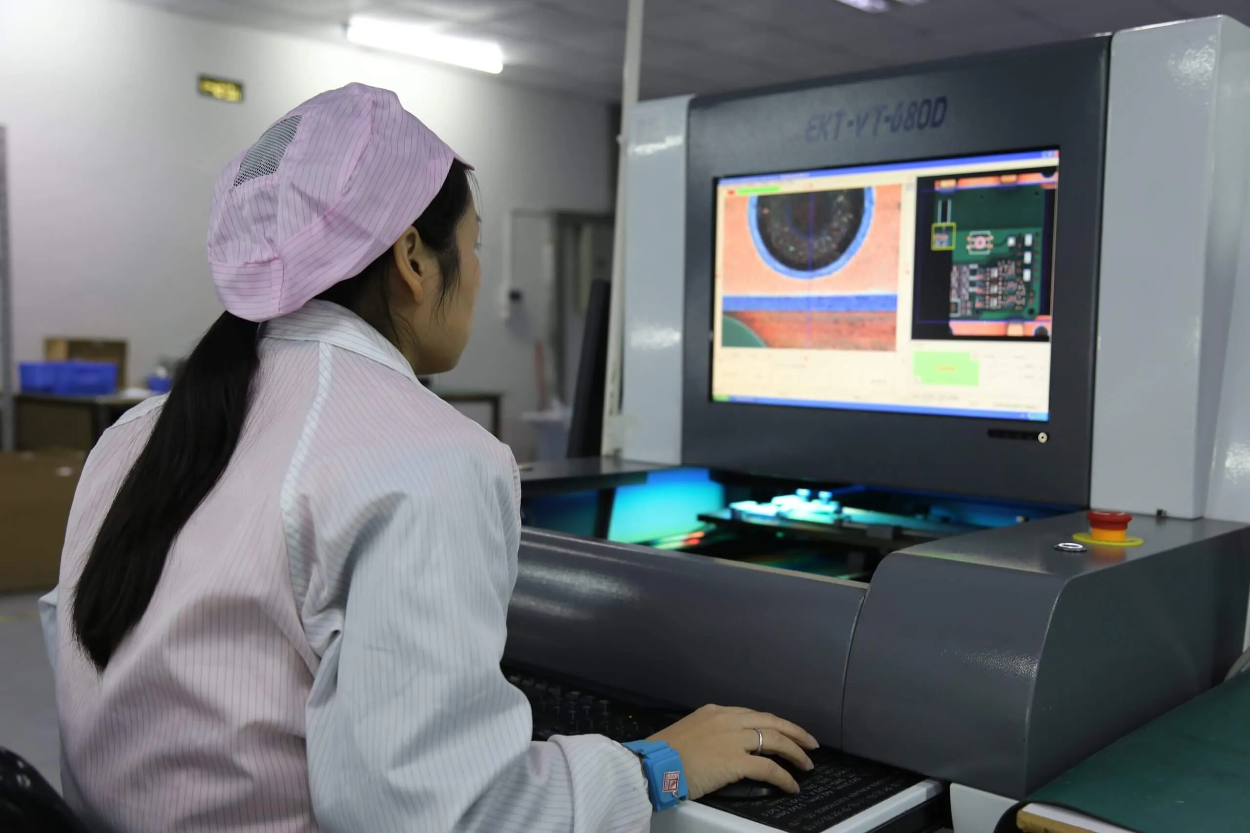
AOI inspection for flex PCBs is a critical quality control step in SMT assembly. AOI systems use high-resolution cameras and advanced algorithms to detect defects such as misaligned components, missing solder, or tombstoning. However, inspecting flexible boards poses unique challenges due to their non-rigid nature.
Here’s how to optimize AOI for flex PCBs:
- Board Flatness: Just like in other steps, securing the board in a fixture during inspection is essential. If the board isn’t flat, the AOI system may misinterpret reflections or shadows as defects, leading to false positives.
- Customized Inspection Parameters: Adjust the AOI software to account for the unique surface characteristics of flex boards. For instance, polyimide materials may have a different reflectivity compared to rigid boards, requiring specific lighting and camera settings.
- Focus on Solder Joints: Since flex boards are often used in applications with high mechanical stress, solder joint quality is critical. AOI systems should be programmed to closely inspect joint integrity, looking for cracks or insufficient solder that could fail under bending or vibration.
- Defect Classification: Train the AOI system to differentiate between actual defects and acceptable variations caused by the board’s flexibility. This reduces unnecessary rework and speeds up the inspection process.
Implementing AOI for flex PCBs can catch up to 95% of assembly defects before the boards move to final testing or deployment. This not only improves product reliability but also saves time and resources by reducing manual inspection needs.
Additional Best Practices for SMT Assembly on Flexible Boards
Beyond the core areas discussed, there are several other best practices to keep in mind for successful SMT assembly on flexible boards:
- Material Handling: Always handle flex boards with care to avoid creasing or tearing. Store them flat or in protective packaging to prevent damage before assembly.
- Protective Coatings: After soldering, apply a conformal coating to protect the board from moisture, corrosion, and mechanical stress. This is especially important for flex boards used in harsh environments, as it can extend their lifespan by up to 50%.
- Testing and Validation: Conduct thorough electrical testing after assembly to verify connections and functionality. Flex boards are often used in compact, high-density designs, so even a single faulty connection can render the entire device unusable.
- Collaboration with Suppliers: Work closely with your material and component suppliers to ensure compatibility. For example, confirm that the solder paste and components are suited for the lower temperature profiles used with flex boards.
By following these practices, you can minimize risks and ensure that your flexible PCBs meet the highest standards of quality and performance.
Conclusion: Achieving Excellence in SMT Assembly for Flexible Boards
Mastering SMT assembly on flexible boards requires attention to detail, specialized equipment, and tailored processes. From addressing pick and place challenges on flex boards to optimizing reflow soldering profiles, stencil design, and AOI for flex PCBs, each step plays a crucial role in the final outcome. By implementing the techniques and best practices outlined in this guide, you can overcome the unique challenges of the SMT process for flexible PCBs and achieve reliable, high-quality results.
Whether you're working on wearables, medical devices, or automotive applications, the right approach to SMT assembly will ensure your flexible boards perform as intended, even under demanding conditions. Keep refining your processes, invest in the right tools, and prioritize precision at every stage to stay ahead in this fast-evolving field.


