 ALLPCB


Flexible printed circuit boards (PCBs) have transformed the electronics industry, offering engineers and designers a versatile solution for modern, compact, and innovative devices. Unlike traditional rigid PCBs, a flexible PCB bends and adapts to unique shapes, making it a cornerstone in applications ranging from wearables to aerospace systems. As technology advances, the demand for lightweight, durable, and space-saving circuitry continues to grow, positioning flexible PCBs as a critical tool for engineers tackling complex design challenges.
In this blog, we'll explore what makes flexible PCBs unique, how they're designed, their key applications, and the advantages they bring to the table. Whether you're an engineer optimizing a prototype or a buyer evaluating options for production, this guide provides actionable insights to help you harness the power of flexible PCBs in your next project.
What is a Flexible PCB?
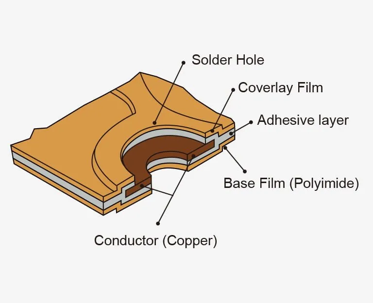
A flexible PCB is a type of printed circuit board made from flexible materials, typically polyimide or polyester, that allow it to bend, twist, and fold without compromising its electrical functionality. Unlike rigid PCBs, which rely on stiff substrates like FR4 (a glass-epoxy compound), flexible PCBs use a malleable base that supports dynamic applications. The conductive traces—usually copper—are laminated onto this substrate, and a protective coverlay (a flexible alternative to solder mask) shields the circuitry.
Flexible PCBs come in several configurations: single-sided, double-sided, or multilayer. For example, a single-sided flexible PCB has one layer of conductive material, ideal for simple designs, while a multilayer version can support complex circuits with up to 20 layers. This adaptability makes them suitable for everything from basic connectors to high-density interconnects (HDI) with trace widths as narrow as 3 mils (0.076 mm).
Key Design Considerations for Flexible PCBs
Designing a flexible PCB requires careful planning to balance flexibility, performance, and manufacturability. Here are the critical factors engineers must consider:
Material Selection
The backbone of any flexible PCB is its substrate. Polyimide, such as DuPont's Kapton, is the most common choice due to its excellent thermal stability (handling temperatures from -200°C to 400°C) and dielectric constant of around 3.4. Polyester is a cost-effective alternative for less demanding applications, though it sacrifices some heat resistance. The choice of copper thickness—typically 0.5 oz (17.5 µm) to 2 oz (70 µm)—also affects flexibility and current-carrying capacity.
Bend Radius and Flexibility
The bend radius—the minimum radius a flexible PCB can tolerate without damage—is a key design parameter. For a single-layer flexible PCB with 1 oz copper, the bend radius is typically 6-10 times the board thickness (e.g., 0.6-1 mm for a 0.1 mm thick board). Multilayer designs require a larger radius, often 12-20 times the thickness, due to increased stiffness. Exceeding this limit risks cracking the copper traces, which can lead to open circuits.
Trace Layout and Impedance Control
Trace design is critical for signal integrity, especially in high-frequency applications. For instance, a 50-ohm impedance—common in RF designs—requires precise trace widths (e.g., 0.2 mm for a 0.1 mm thick polyimide substrate) and spacing. Misalignment or overly tight bends can introduce signal loss or crosstalk, degrading performance. Engineers often use simulation tools like Computer-Aided Engineering (CAE) software to optimize layouts.
Stiffeners and Coverlay
To support components or connectors, stiffeners—made of FR4 or polyimide—are added to specific areas of a flexible PCB. These stiffeners, typically 0.5-1.5 mm thick, prevent flexing where rigidity is needed, such as at a zero-insertion-force (ZIF) connector. The coverlay, applied via lamination or adhesive, protects traces and maintains flexibility, unlike the rigid solder mask used on traditional PCBs.
Dive into best practices: Flexible PCB Design: Best Practices for Bendable Circuit Applications
Manufacturing Process of Flexible PCBs
Producing a flexible PCB involves specialized techniques to ensure durability and precision. Here's a step-by-step overview:
- Substrate Preparation: The process begins with a roll of polyimide or polyester film, typically 25-125 µm thick. This material is cleaned and pre-treated to enhance adhesion for copper lamination.
- Copper Lamination: A thin copper foil (e.g., 18 µm or 35 µm) is bonded to the substrate using heat and pressure. For double-sided or multilayer designs, this step is repeated with precise alignment.
- Photolithography: A photoresist layer is applied, exposed to UV light through a mask, and developed to define the circuit pattern. The unwanted copper is then etched away, leaving the desired traces.
- Coverlay Application: A flexible coverlay film, pre-cut with openings for pads, is laminated over the traces. This step requires accuracy to avoid misalignment, which could expose or damage the circuitry.
- Drilling and Plating: Micro-vias or through-holes (as small as 0.1 mm) are drilled using lasers, then plated with copper to connect layers in multilayer designs. This step is crucial for HDI flexible PCBs.
- Final Assembly: Stiffeners, if needed, are attached, and the board is tested for continuity and performance. Flying probe testing, for example, verifies electrical connectivity with a resolution down to 0.05 mm.
The result is a lightweight, flexible circuit ready for integration into a device. The process demands advanced equipment—like laser drills capable of 10 µm precision—to meet modern design tolerances.
Read the full process here: Flexible PCB Manufacturing: A Step-by-Step Guide
SMT Assembly on Flexible PCBs: Challenges and Best Practices
Surface Mount Technology (SMT) assembly on flexible printed circuit boards (flex PCBs) is a critical process that enables miniaturized and lightweight electronics across industries like medical, consumer wearables, aerospace, and automotive. However, the inherent bendability and thinness of flex substrates introduce unique challenges not present in rigid board assemblies. Below is an in-depth look at these challenges, along with proven best practices for successful implementation.
Get the techniques: Mastering SMT Assembly on Flexible Boards: Techniques and Best Practices
Comparing PCB Types: Rigid, Flexible, and Rigid-Flex
When deciding between different PCB types, understanding their characteristics is crucial. While rigid PCBs offer structural strength and cost-efficiency, flexible PCBs excel in tight spaces and dynamic environments. Rigid-flex PCBs combine the strengths of both.
Rigid PCBs are the most traditional and commonly used type. They’re built from solid, inflexible materials such as FR-4 (a fiberglass-reinforced epoxy laminate), aluminum, or ceramic. Once manufactured, these boards cannot be bent or twisted without breaking.
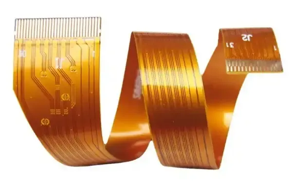
Flexible PCBs (FPCs) use materials like polyimide or PET film to allow bending, folding, and even dynamic movement during operation. They’re ideal for high-density designs in constrained spaces.
Rigid-Flex PCBs combine the benefits of both rigid and flexible PCBs into a single design. These boards contain multiple layers of flexible circuitry laminated onto rigid boards, enabling both strength and flexibility where needed.
Read more: The Differences Between Rigid, Flexible, and Rigid-Flex PCBs
Applications of Flexible PCBs
The versatility of flexible PCBs makes them indispensable across industries. Here are some standout examples:
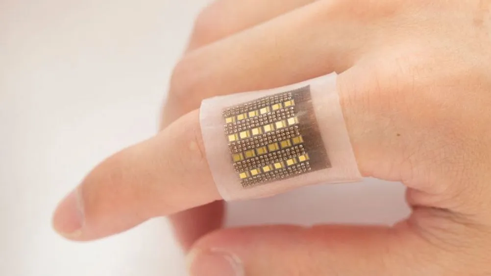
Wearable Technology
In smartwatches and fitness trackers, flexible PCBs conform to curved surfaces, reducing device size and weight. A typical wearable might use a double-sided flexible PCB with a 0.2 mm thickness, supporting sensors and Bluetooth modules while enduring repeated flexing (up to 100,000 cycles).
Read more: Flexible PCB Design for Medical Wearables: Balancing Performance and Biocompatibility
Medical Devices
Medical imaging devices like ultrasound probes benefit immensely from flexible PCBs, thanks to their ability to conform to 3D shapes and route signals in compact form factors.
Read more: Flexible PCBs for Ultrasound Transducer Interconnects: Design and Manufacturing Considerations
Automotive Systems
In automotive applications, such as camera modules or LIDAR systems, flexible PCBs withstand vibration and heat (up to 150°C). Their ability to wrap around tight spaces cuts assembly time by 20-30% compared to rigid boards with wire harnesses.
See more: Bending the Rules: How Flexible PCBs are Revolutionizing Automotive Electronics Manufacturing
Consumer Electronics
Flexible PCBs have become a cornerstone in the advancement of foldable phones and next-gen consumer electronics, enabling new device form factors that were once unimaginable. These circuits offer bendability, durability, and space-saving integration—perfect for devices that need to flex, twist, or fold while maintaining reliable electrical performance.
See more: Flexible PCBs for Foldable Phones: Design and Manufacturing Innovations
Driving Sustainability with Bio-Based Flexible PCBs
As the demand for environmentally responsible electronics grows, bio-based flexible PCBs are emerging as a promising solution that combines performance with sustainability. Traditional flex PCBs rely heavily on petroleum-based substrates like polyimide (PI) and polyester (PET), which are not biodegradable and pose long-term environmental challenges. In contrast, bio-based alternatives aim to reduce carbon footprints, improve recyclability, and support circular economy principles in electronic design and manufacturing.
With growing investment in green electronics, research institutions and industry players are actively improving the heat resistance, printability, and durability of bio-based PCB materials. Innovations like hybrid substrates (combining cellulose with graphene or nanoclays) or enzyme-triggered degradation circuits offer new pathways to scale adoption.
Major electronics OEMs are also beginning to integrate bio-based PCBs in their sustainability roadmaps, especially as e-waste regulations tighten worldwide.
Suggested Reading: Bio-Based Flexible PCBs: A New Frontier in Sustainable Electronics
Advantages of Flexible PCBs
Why choose a flexible PCB over a rigid one? The benefits are clear and impactful:
Space and Weight Savings
Flexible PCBs require only about 10% of the space and weight of a rigid PCB assembly. For instance, a 50 g rigid board with connectors might be replaced by a 5 g flexible PCB, streamlining packaging in portable devices.
Enhanced Reliability
Fewer interconnects mean fewer points of failure. A flexible PCB eliminates solder joints and crimps found in wire harnesses, reducing failure rates by up to 15% in high-vibration environments like automotive systems.
Design Freedom
Engineers can bend and fold flexible PCBs to fit unconventional shapes, enabling innovative designs. This flexibility supports tighter bend radii (e.g., 0.5 mm for thin substrates), opening up new possibilities in miniaturization.
Thermal and Electrical Performance
Polyimide's heat dissipation outperforms FR4, allowing flexible PCBs to handle higher currents—up to 20% more per unit weight of copper. Their dielectric properties also support high-speed signals, with losses as low as 0.02 dB/cm at 1 GHz.
How ALLPCB Supports Flexible PCB Projects
For engineers and buyers looking to bring flexible PCB designs to life, partnering with a reliable manufacturer is key. ALLPCB excels in quick-turn prototyping, delivering flexible PCBs in as little as 72 hours for simple designs. Our advanced manufacturing capabilities—like laser drilling for 10 µm vias and HDI expertise—ensure precision for complex multilayer boards. Plus, with global logistics, we streamline delivery to keep your project on schedule, whether you're in prototyping or full production.
Conclusion
Flexible PCBs are more than just an alternative to rigid boards—they're a game-changer for engineers pushing the boundaries of design. From their ability to save space and weight to their unmatched flexibility in challenging environments, flexible PCBs empower innovation across industries. By mastering their design principles and understanding their applications, you can unlock new possibilities for your next project.
Ready to explore flexible PCBs further? Dive into your design tools, test a prototype, or reach out to a trusted manufacturer to see how this technology can elevate your work. The future of electronics is flexible—let's build it together.


