 ALLPCB


In modern printed circuit board (PCB) design, ensuring stable power delivery and minimizing noise are critical for high-performance electronics. Power plane segmentation and decoupling capacitor placement are two key strategies that engineers use to achieve power integrity and signal reliability. These techniques address challenges like electromagnetic interference (EMI), voltage fluctuations, and high-frequency noise, which can degrade circuit performance. In this blog, we explore the principles, best practices, and practical tips for implementing power plane segmentation and decoupling capacitor placement, offering actionable insights for engineers designing robust PCBs.
Understanding Power Plane Segmentation
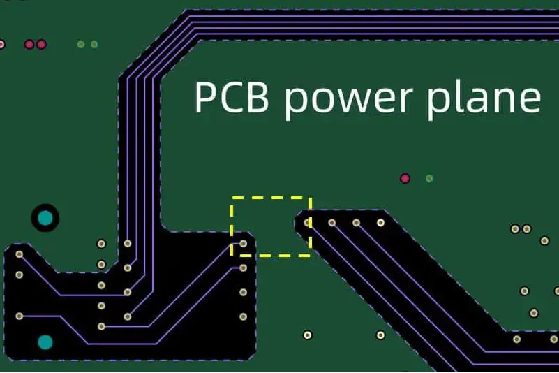
Power plane segmentation involves dividing a large, continuous power plane into smaller, isolated sections or 'islands' to supply different circuits or voltage domains on a PCB. This approach reduces noise coupling between circuits, minimizes transmission line resonances, and enhances power integrity. By isolating power domains, segmentation prevents high-frequency noise from one circuit, such as a high-speed digital processor, from interfering with sensitive analog components.
Segmentation is particularly effective in multilayer PCBs, where power and ground planes are common. For example, a 3.3V power plane might be split into separate segments for digital and analog circuits to prevent cross-coupling. Each segment is typically connected to the main power source through a series choke, such as a ferrite bead with an impedance of 10-50 ohms in the VHF range, to isolate high-frequency noise.
Benefits of Power Plane Segmentation
- Reduced Noise Coupling: By isolating power domains, segmentation prevents noise from propagating across the board. For instance, a noisy digital circuit operating at 800 MHz won't affect a sensitive RF circuit on the same PCB.
- Improved EMI Performance: Segmentation pushes transmission line resonances into higher frequency ranges (e.g., GHz), where they are less likely to cause EMI issues.
- Enhanced Power Integrity: Smaller power plane segments reduce impedance variations, ensuring stable voltage delivery to components.
Design Considerations for Segmentation
When segmenting power planes, engineers must carefully plan the layout to avoid unintended consequences. Here are key considerations:
- Follow Circuit Boundaries: Align segmentation boundaries with natural divisions in the circuit, such as clock distribution networks or functional blocks, to minimize cross-talk.
- Inset Power Plane Edges: To reduce edge radiation, inset the power plane edge from the ground plane by at least 10 times the dielectric thickness (e.g., 40 mils for a 4-mil dielectric).
- Use Series Chokes: Incorporate ferrite beads or inductors to connect segments to the main power supply, ensuring high-frequency isolation without affecting DC performance.
- Simulate Resonances: Use tools like SPICE or electromagnetic simulation software to analyze resonant frequencies, as segmentation can shift resonances to higher, less harmful ranges.
The Role of Decoupling Capacitors in PCB Design
Decoupling capacitors are essential for maintaining power integrity by stabilizing voltage levels and suppressing high-frequency noise in the power distribution network (PDN). They act as local energy reservoirs, supplying instantaneous current to integrated circuits (ICs) during transient demands, such as when a processor switches at 1 GHz. Without proper decoupling, voltage fluctuations can lead to signal degradation, EMI issues, or even system failures.
Decoupling capacitors come in two main types:
- Bulk Capacitors: These large-valued capacitors (e.g., 10 µF to 100 µF) handle low-frequency noise (below a few hundred kHz) and provide global decoupling for the entire board.
- High-Frequency Capacitors: Smaller capacitors (e.g., 0.01 µF to 0.1 µF) target high-frequency noise (up to 100 MHz) and are placed close to IC power pins for local decoupling.
Why Decoupling Capacitors Matter
Decoupling capacitors address several critical issues in PCB design:
- Voltage Stability: They absorb excess charge when voltage spikes occur and release charge during voltage drops, maintaining a stable supply (e.g., within ±5% of 3.3V).
- Noise Suppression: Capacitors filter out high-frequency noise, preventing it from coupling into signal lines or radiating as EMI.
- Ground Bounce Reduction: By counteracting voltage spikes caused by parasitic inductance in IC packages, capacitors minimize ground bounce, ensuring consistent signal levels.
Best Practices for Decoupling Capacitor Placement
Effective decoupling capacitor placement is critical for minimizing loop inductance and ensuring optimal performance. Here are proven guidelines to follow:
1. Place Capacitors Close to IC Power Pins
To minimize parasitic inductance, place high-frequency decoupling capacitors as close as possible to the IC's power pins. For high-speed circuits operating above 1 GHz, the distance should ideally be less than one-tenth of a quarter wavelength at the capacitor's self-resonant frequency (SRF). For example, a 0.1 µF capacitor with an SRF of 100 MHz should be within 0.375 inches of the power pin.
2. Use Multiple Capacitors for Broad Frequency Coverage
A single capacitor cannot suppress noise across all frequencies due to its SRF. Instead, use a combination of capacitors with different values (e.g., 0.001 µF, 0.01 µF, 0.1 µF) to cover a wide frequency range. For instance, two 0.1 µF capacitors in parallel have lower equivalent series inductance (ESL) than a single 0.2 µF capacitor, improving high-frequency performance.
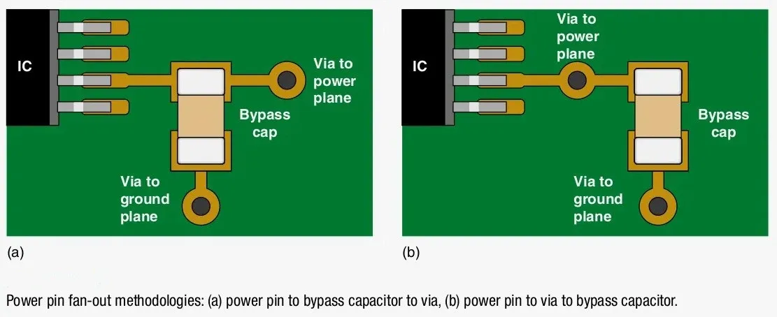
3. Minimize Loop Inductance
The effectiveness of a decoupling capacitor depends on the loop area formed by the capacitor, its vias, and the power/ground planes. To reduce inductance:
- Use short, wide traces (e.g., 10 mils wide for 2 oz copper) between the capacitor and IC pins.
- Place vias connecting the capacitor to power and ground planes as close together as possible (e.g., 10 mils apart).
- For high-speed designs, consider via-in-pad technology for ball grid array (BGA) packages to shorten the current path.
4. Optimize for Closely Spaced Power Planes
In PCBs with closely spaced power and ground planes (e.g., 4 mils or less), the inter-plane capacitance (approximately 16 pF/cm² for FR-4 material at 10 mils spacing) provides a low-impedance path for high-frequency currents. In such cases, the exact placement of decoupling capacitors is less critical, as the planes themselves act as distributed capacitance. However, capacitors should still be distributed evenly across the board to support transient currents.
5. Consider Capacitor Package Size
Smaller capacitor packages, such as 0402 or 0603, have lower ESL and are preferred for high-frequency decoupling. Choose the largest nominal capacitance available in the smallest package to maximize performance without exceeding the inter-plane capacitance. For example, a 0.01 µF 0402 capacitor is often ideal for local decoupling.
Common Myths and Misconceptions
Several myths about decoupling capacitor placement can lead to suboptimal designs. Let's debunk a few:
- Myth: One Capacitor Per Power Pin: While older guidelines suggested placing a 0.1 µF capacitor for each power pin, modern high-speed ICs with dozens of power pins require a more strategic approach. Using too many capacitors can increase board complexity and cost without significant benefits. Instead, optimize the number and placement based on PDN impedance simulations.
- Myth: Ultra-Low Inductance Capacitors Are Always Better: While low-inductance capacitors sound appealing, their benefits are limited if connected through high-inductance vias or traces. Standard 0402 or 0603 capacitors with well-designed connections often perform just as well.
- Myth: Capacitor Placement Doesn't Matter with Power Planes: While closely spaced planes reduce the importance of precise capacitor placement, strategic distribution is still necessary to handle transient currents and maintain power stability across the board.
Advanced Techniques for Power Integrity
For high-speed or mixed-signal designs, additional techniques can enhance power plane segmentation and decoupling:
- Embedded Capacitance: Use thin dielectric materials (e.g., 2 mils) between power and ground planes to create distributed capacitance, reducing the need for discrete capacitors at frequencies above 100 MHz.
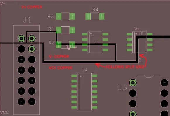
- Power Plane Segmentation for Mixed-Signal Designs: Isolate analog and digital power planes to prevent noise coupling. For example, use separate 3.3V planes for analog and digital sections, each with its own decoupling capacitors (e.g., 1 µF for analog, 0.1 µF for digital).
- Active Decoupling: In extremely high-frequency applications (e.g., 5G RF circuits), active circuits can dynamically compensate for voltage fluctuations, supplementing passive capacitors.
Conclusion
Power plane segmentation and decoupling capacitor placement are cornerstone techniques for achieving power integrity in PCB design. By segmenting power planes to isolate noise and strategically placing decoupling capacitors to stabilize voltage, engineers can create reliable, high-performance circuits. Key practices include placing capacitors close to IC pins, minimizing loop inductance, and leveraging closely spaced planes for distributed capacitance. Advanced techniques like embedded capacitance and active decoupling further enhance performance in demanding applications. By following these guidelines and debunking common myths, you can optimize your PCB designs for power stability and signal integrity.


