 ALLPCB


In the fast-evolving world of technology, edge computing has become a game-changer, bringing data processing closer to the source for faster response times and reduced latency. A key component in making edge devices efficient and compact is the use of flexible PCBs (Printed Circuit Boards). But what exactly goes into designing a flexible PCB for edge computing, and why are they so important? In this blog, we’ll explore the applications of flexible PCBs in edge devices, critical design considerations, and how they contribute to performance and reliability. Whether you’re an engineer or a tech enthusiast, this guide will provide actionable insights into flexible PCB design for edge computing.
What Are Flexible PCBs and Why Use Them in Edge Computing?
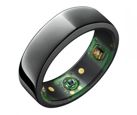
Flexible PCBs, often called flex PCBs, are circuit boards made from bendable materials that allow them to conform to unique shapes and fit into tight spaces. Unlike traditional rigid PCBs, flex PCBs can twist, fold, and bend without breaking, making them ideal for compact and portable devices. In edge computing, where devices like IoT sensors, wearables, and industrial equipment need to operate in constrained or dynamic environments, flexible PCBs offer unmatched versatility.
Edge computing focuses on processing data locally rather than relying on distant cloud servers. This requires hardware that is not only powerful but also lightweight, durable, and space-efficient. Flexible PCBs meet these demands by enabling innovative designs and ensuring reliability in harsh conditions. Let’s dive deeper into their applications and the specific considerations for designing them.
Applications of Flexible PCBs in Edge Computing
Flexible PCBs are transforming edge computing by enabling a wide range of applications. Here are some key areas where they shine:
- IoT Devices: Internet of Things (IoT) devices, such as smart sensors and home automation systems, often need to fit into small or irregularly shaped spaces. Flexible PCBs allow for compact designs without sacrificing functionality. For instance, a smart thermostat can use a flex PCB to wrap around internal components, saving space.
- Wearable Technology: Edge computing is critical in wearables like fitness trackers and medical monitoring devices. These gadgets process data in real-time to provide instant feedback. A bendable PCB for edge devices ensures the hardware can conform to the shape of a wristband or clothing while maintaining signal integrity.
- Industrial Automation: Edge devices in factories often operate in harsh environments with vibration, heat, and dust. Flexible PCBs can withstand these conditions better than rigid boards due to their ability to absorb stress and resist cracking. They’re used in robotic arms and monitoring systems to ensure consistent performance.
- Automotive Systems: Modern vehicles rely on edge computing for features like driver assistance and real-time diagnostics. Flexible PCBs are used in dashboard displays and sensor modules, where they can bend around tight corners and endure temperature fluctuations.
Key Benefits of Using Flex PCBs in Edge Applications
Before we get into the design considerations, let’s highlight why flex PCBs are a top choice for edge computing:
- Space Efficiency: Flex PCBs can be folded or layered, reducing the overall footprint of a device. This is crucial for edge devices where every millimeter counts.
- Durability: Their ability to bend without breaking makes them more resistant to mechanical stress, improving the reliability of flex PCBs in dynamic environments.
- Lightweight Design: Flex PCBs are often thinner and lighter than rigid boards, which is essential for portable edge devices.
- Cost-Effective Assembly: By reducing the need for connectors and cables, flex PCBs can lower assembly costs and improve signal reliability.
Design Considerations for Flexible PCBs in Edge Computing
Designing a flexible PCB for edge computing requires careful planning to ensure performance, durability, and compatibility with the unique demands of edge applications. Below, we’ll break down the critical factors to consider when working on flexible PCB design for edge computing.
1. Choosing the Right Flex PCB Materials
The foundation of any flexible PCB lies in its materials. The substrate and conductive layers must balance flexibility, thermal stability, and electrical performance. Here are the primary materials used:
- Polyimide (PI): This is the most common substrate for flex PCBs due to its excellent thermal resistance (up to 260°C) and flexibility. It’s ideal for edge devices exposed to high temperatures, such as automotive sensors.
- Polyester (PET): A more cost-effective option, PET is less heat-resistant than polyimide but works well for low-temperature applications like consumer wearables.
- Copper Foils: Rolled annealed (RA) copper is preferred for flex PCBs because it can endure repeated bending without cracking. Typical thicknesses range from 18 to 35 micrometers, depending on current requirements.
When selecting materials, consider the operating environment of the edge device. For instance, an industrial edge sensor may need polyimide to handle heat, while a fitness tracker could use PET to keep costs down.
2. Bend Radius and Flexibility
One of the biggest challenges in flexible PCB design is ensuring the board can bend without damaging traces or components. The bend radius—the minimum radius a PCB can be bent without stress—plays a critical role. A general rule of thumb is that the bend radius should be at least 10 times the thickness of the PCB for dynamic flexing (repeated bending) and 3 times for static flexing (one-time bending during installation).
For edge devices like wearables, where the PCB might bend frequently, designers must minimize stress on copper traces by using thinner materials and avoiding sharp angles. Software tools can simulate bending stress to optimize the layout before manufacturing.
3. Signal Integrity and Impedance Control
Edge computing devices often handle high-speed data processing, making signal integrity a top priority. Flexible PCBs can introduce challenges like signal loss or crosstalk due to their thin structure and bending. To address this:
- Maintain consistent impedance, typically around 50 ohms for high-speed signals, by controlling trace width and spacing.
- Use ground planes to shield signals and reduce electromagnetic interference (EMI), which is critical for edge devices operating near other electronics.
- Avoid routing high-speed traces through bend areas, as flexing can alter impedance and cause signal degradation.
For example, an edge computing module in a smart factory might process data at speeds exceeding 1 Gbps. Ensuring impedance matching and minimizing signal loss in the flex PCB design is essential for reliable operation.
4. Thermal Management
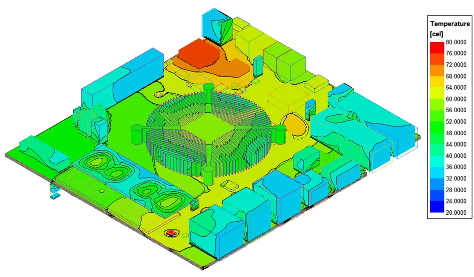
Edge devices often operate in environments with varying temperatures, and flex PCBs must handle heat dissipation effectively. Unlike rigid boards, flex PCBs have limited surface area for heat sinks, so designers must get creative:
- Use thermally conductive adhesives or coatings to transfer heat away from critical components.
- Space out heat-generating components to avoid hotspots, especially in areas prone to bending.
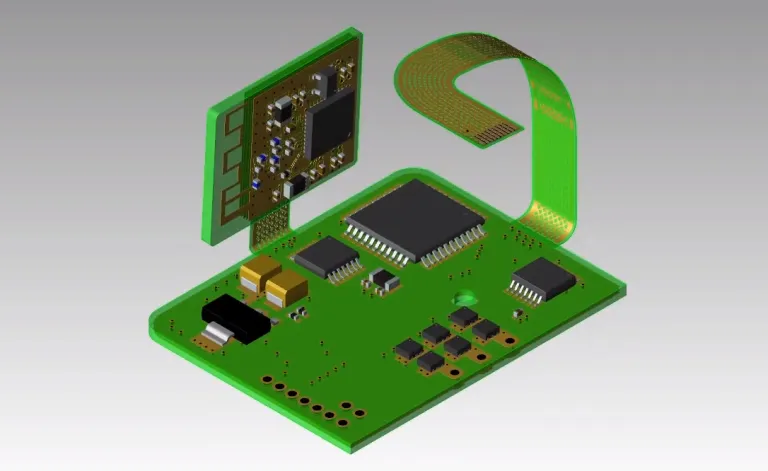
- Consider hybrid designs that combine flex and rigid sections, allowing heat sinks on rigid areas for better cooling.
For instance, an edge device in an automotive system might experience temperatures from -40°C to 85°C. Proper thermal design ensures the flex PCB remains reliable under these extremes.
5. Reliability and Durability Testing
The reliability of flex PCBs is paramount, especially for edge computing applications where downtime can be costly. Rigorous testing ensures the PCB can withstand the stresses of bending, temperature changes, and environmental factors. Key tests include:
- Bend Cycle Testing: Simulates repeated flexing to ensure the board can handle thousands of cycles without failure. For dynamic applications, aim for at least 10,000 cycles.
- Thermal Cycling: Exposes the PCB to extreme temperature swings to verify material stability.
- Environmental Testing: Assesses performance in humidity, dust, and vibration, which are common in industrial edge settings.
By prioritizing reliability testing, designers can ensure that a bendable PCB for edge devices performs consistently over its lifespan.
6. Component Placement and Assembly
Placing components on a flexible PCB requires careful thought, as bending can stress solder joints and lead to failures. Here are some best practices:
- Avoid placing heavy or rigid components in bend areas. Instead, position them in stable, non-flexing zones.
- Use smaller, lightweight components to minimize mechanical stress. For example, opt for 0402 or 0201 SMD packages instead of larger ones.
- Reinforce solder joints with adhesives in high-stress areas to prevent cracking during flexing.
Assembly processes should also account for the flexibility of the board. Automated pick-and-place machines may need adjustments to handle flex PCBs without causing damage.
Challenges in Flexible PCB Design for Edge Computing
While flex PCBs offer many advantages, they come with unique challenges that designers must overcome:
- Higher Manufacturing Costs: Flex PCBs are often more expensive to produce than rigid boards due to specialized materials and processes. However, the reduction in connectors and assembly costs can offset this in the long run.
- Complex Design Rules: Designing for flexibility adds layers of complexity, such as managing bend radii and ensuring signal integrity, which can extend development time.
- Limited Component Compatibility: Not all components are suitable for flex PCBs, especially those sensitive to mechanical stress or requiring heavy heat sinks.
By understanding these challenges upfront, engineers can plan accordingly and mitigate risks during the design phase.
Future Trends: Flex PCBs and Edge Computing
As edge computing continues to grow, so will the demand for advanced flexible PCB solutions. Emerging trends include:
- 5G Integration: Edge devices supporting 5G networks will require flex PCBs with even tighter impedance control and higher signal speeds, pushing the boundaries of design.
- Miniaturization: As edge devices become smaller, flex PCBs will need to pack more functionality into tighter spaces without compromising performance.
- Sustainable Materials: The industry is exploring eco-friendly flex PCB materials to reduce environmental impact while maintaining reliability.

Conclusion
Flexible PCBs are a cornerstone of modern edge computing, enabling compact, durable, and high-performing devices across industries like IoT, wearables, automotive, and industrial automation. By focusing on critical design considerations—such as material selection, bend radius, signal integrity, and thermal management—engineers can create reliable and efficient solutions tailored to the unique demands of edge applications. While challenges like cost and design complexity exist, the benefits of space savings, durability, and versatility make flex PCBs an invaluable choice.
Whether you’re working on a bendable PCB for edge devices or exploring flex PCB applications in edge computing, understanding these principles is key to success. With careful planning and testing, flexible PCBs can unlock new possibilities for innovation in the fast-paced world of edge technology.


