 ALLPCB


In the world of printed circuit board (PCB) design, managing heat is critical to ensuring performance and reliability. If you're searching for solutions related to PCB thermal management, heat dissipation PCB techniques, or high-power PCB design, you're in the right place. This blog dives deep into thermal considerations in PCB form factor design, offering practical tips and strategies like thermal vias and PCB cooling techniques to keep your circuits cool and efficient.
Heat buildup in PCBs can lead to component failure, reduced lifespan, and performance issues. Whether you're designing for consumer electronics or industrial applications, understanding how to manage heat through smart design choices is essential. In this post, we'll explore why thermal management matters, key design factors, and actionable methods to dissipate heat effectively.
Why Thermal Management Matters in PCB Design
Every electronic device generates heat during operation, especially in high-power applications. Active components like processors, power transistors, and voltage regulators can reach junction temperatures above 100°C if not managed properly. When heat isn't dissipated efficiently, it can cause thermal stress, degrade materials, and even lead to system failure.
For instance, a typical microprocessor might have a maximum safe operating temperature of 85°C. If the surrounding PCB can't conduct heat away, the component could overheat, leading to erratic behavior or permanent damage. Effective PCB thermal management ensures that heat flows away from critical components, maintaining safe operating conditions and extending the device's lifespan.
Key Factors Affecting Heat Dissipation in PCB Form Factor Design
The form factor of a PCB—its size, shape, and layout—plays a significant role in how heat is managed. Smaller boards, while space-efficient, often struggle with heat dissipation due to limited surface area. Larger boards may offer more room for cooling solutions but can introduce other design challenges. Let's break down the key factors that influence heat dissipation PCB performance.
1. Board Size and Component Density
Smaller PCBs with densely packed components are prone to overheating because there's less space for heat to spread out. For example, a compact IoT device with a 2-inch by 2-inch board might have multiple high-power chips in close proximity, creating localized hot spots. Increasing board size can help, but when that's not an option, designers must use other PCB cooling techniques to manage heat.
2. Material Selection
The materials used in a PCB directly impact its thermal conductivity. Standard FR-4 substrates, commonly used in PCBs, have a low thermal conductivity of about 0.3 W/m·K, meaning they don't transfer heat well. For high-power PCB design, consider using materials with higher thermal conductivity, such as metal-core PCBs (MCPCBs) with aluminum or copper bases, which can reach thermal conductivities of 1-2 W/m·K or higher.
3. Layer Stack-Up and Thickness
Multi-layer PCBs can trap heat between layers if not designed with thermal paths in mind. Thicker copper layers (e.g., 2 oz or 70 μm instead of the standard 1 oz or 35 μm) improve heat spreading due to copper's high thermal conductivity of approximately 400 W/m·K. Strategically placing ground planes or power planes near heat-generating components can also act as a heat sink, distributing thermal energy across the board.
Effective PCB Cooling Techniques for Thermal Management
Now that we understand the factors at play, let's explore practical PCB cooling techniques to improve heat dissipation. These methods can be passive (relying on natural heat transfer) or active (using external mechanisms), depending on the application's needs.
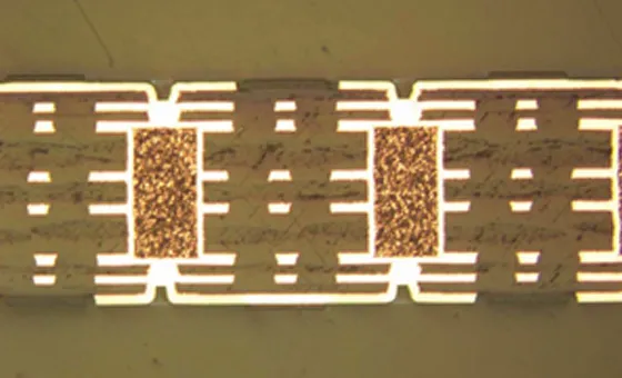
1. Incorporating Thermal Vias
Thermal vias are small holes filled or plated with conductive material, typically copper, that transfer heat from one side of the PCB to the other or to a heat sink. They act like thermal "highways," moving heat away from hot components. For example, placing an array of thermal vias under a high-power LED chip can reduce its junction temperature by 10-15°C, significantly improving performance.
When designing with thermal vias, use a grid pattern (e.g., 0.3 mm diameter vias spaced 1.2 mm apart) to maximize heat transfer without compromising structural integrity. However, avoid overusing vias near signal traces to prevent interference with electrical performance.
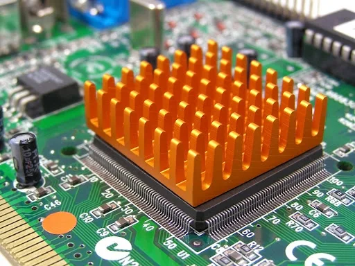
2. Using Heat Sinks and Thermal Pads
Heat sinks are metal structures attached to components to absorb and dissipate heat into the surrounding air. For a power transistor dissipating 5W of heat, a small aluminum heat sink with fins can reduce the component temperature by 20-30°C. Thermal pads or interface materials with high thermal conductivity (e.g., 3-5 W/m·K) ensure efficient heat transfer between the component and the heat sink.
In high-power PCB design, ensure the heat sink is properly sized and mounted to handle the thermal load. Lightweight designs may suffice for low-power applications, while larger, fan-assisted heat sinks might be necessary for industrial systems.
3. Optimizing Component Placement
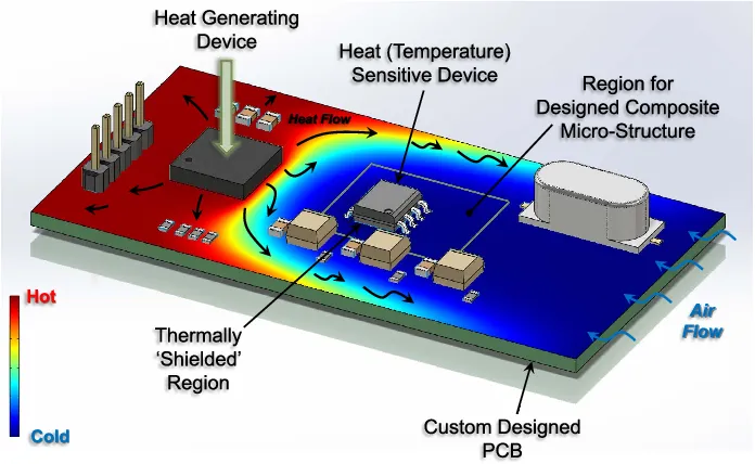
Strategic placement of components can prevent heat buildup. Place high-power components away from each other to avoid creating concentrated hot spots. For instance, spacing two power regulators 10 mm apart on a board can lower their combined thermal impact compared to placing them side by side. Additionally, position heat-sensitive components, like sensors, far from heat sources to maintain accuracy.
4. Enhancing Airflow with Ventilation
In enclosed systems, trapped heat can quickly raise PCB temperatures. Designing enclosures with ventilation slots or cutouts allows natural convection to carry heat away. For a small consumer device, adding vents near a PCB hotspot can reduce internal temperatures by 5-10°C. In more demanding setups, active cooling with fans might be necessary to force air over critical areas.
Advanced Strategies for High-Power PCB Design
For applications involving significant power loads, such as electric vehicle controllers or industrial power supplies, basic cooling methods may not suffice. Here are advanced strategies tailored for high-power PCB design to tackle extreme thermal challenges.
1. Metal-Core PCBs for Superior Heat Dissipation
As mentioned earlier, metal-core PCBs use a metal base layer (often aluminum) to conduct heat away from components. These boards are ideal for high-power LED lighting or motor control systems, where heat dissipation is a constant concern. A typical aluminum-core PCB can handle thermal loads up to 10 times higher than standard FR-4, making it a go-to choice for demanding projects.
2. Embedded Heat Pipes
Heat pipes are hollow tubes filled with a working fluid that transfers heat through evaporation and condensation. Embedding heat pipes into a PCB or attaching them to critical areas can move heat to a cooler part of the board or an external heat sink. This technique is especially useful in compact, high-density designs where traditional cooling methods are limited.
3. Active Cooling Systems
For extreme cases, active cooling systems like Peltier coolers or liquid cooling can be integrated into the design. While these solutions add complexity and cost, they are effective for applications with power dissipation exceeding 50W per component. Liquid cooling, for instance, can maintain temperatures below 50°C even in high-performance computing systems.
Design Tips for Balancing Thermal and Electrical Performance
While focusing on PCB thermal management, it's easy to overlook electrical performance. Over-emphasizing heat dissipation can lead to signal integrity issues or increased manufacturing costs. Here are some tips to strike the right balance.
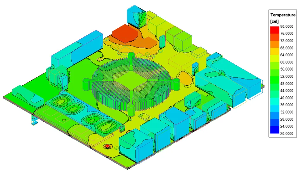
- Simulate Thermal Behavior: Use design software to model heat distribution before fabrication. Tools can predict hot spots and help optimize thermal vias or copper plane placement with minimal impact on signal paths.
- Prioritize Ground Planes: Large ground planes not only improve electrical grounding but also act as heat spreaders. A solid copper ground plane can reduce localized temperatures by 5-10°C.
- Minimize Thermal Resistance: Ensure tight contact between components and cooling elements like heat sinks or thermal pads to reduce thermal resistance, which can otherwise bottleneck heat transfer.
Common Mistakes to Avoid in PCB Thermal Management
Even experienced designers can make errors that undermine heat dissipation PCB efforts. Here are some pitfalls to watch out for.
- Ignoring Thermal Expansion: Different materials expand at different rates when heated. Mismatches between the PCB substrate and components can cause mechanical stress or cracks over time.
- Overloading Thermal Vias: Too many vias in a small area can weaken the board or disrupt signal routing. Balance thermal needs with structural and electrical requirements.
- Neglecting Ambient Conditions: A PCB designed for room temperature operation might fail in a hot industrial environment. Always consider the operating environment during design.
Conclusion: Building Cooler, More Reliable PCBs
Thermal considerations in PCB form factor design are non-negotiable for ensuring the reliability and performance of electronic devices. By focusing on PCB thermal management, leveraging heat dissipation PCB strategies, and applying PCB cooling techniques like thermal vias, you can prevent overheating and extend the life of your circuits. For high-power PCB design, advanced solutions such as metal-core boards and active cooling systems provide the extra edge needed for demanding applications.
Designing with heat in mind doesn't have to be complicated. Start with the basics—material selection, component placement, and thermal vias—and scale up to advanced methods as needed. With these strategies, you can keep your circuits cool and your projects running smoothly.


