ALLPCB


Designing a printed circuit board (PCB) for an infotainment system can be a complex task. These systems, often found in vehicles, combine audio, video, navigation, and connectivity features, requiring robust and reliable PCB designs. However, issues like signal noise, power distribution problems, and layout errors can lead to performance failures. In this comprehensive guide, we’ll walk you through troubleshooting common issues in infotainment system PCB design, focusing on practical solutions for infotainment PCB failure analysis, debugging PCB layout problems, signal noise troubleshooting, and power distribution issues PCB. Let’s dive into the details to help you build better, more reliable designs.
Why Infotainment System PCBs Are Prone to Issues
Infotainment systems are at the heart of modern vehicles, handling everything from touchscreen displays to Bluetooth connectivity. These systems operate in a challenging environment with high temperatures, vibrations, and electromagnetic interference (EMI). The PCBs within these systems must manage high-speed signals, multiple power domains, and tight space constraints, making them susceptible to various failures. Understanding the root causes of these problems is the first step in effective troubleshooting.
Common Issues in Infotainment System PCB Design
Let’s break down the most frequent problems encountered in infotainment system PCB design and explore actionable solutions for each. Whether you’re dealing with signal integrity or power issues, these insights will help you diagnose and fix problems efficiently.
1. Signal Noise and Interference in Infotainment PCBs
Signal noise is a major concern in infotainment systems due to the presence of high-speed digital signals and sensitive analog components. Noise can disrupt audio quality, cause screen flickering, or interfere with wireless communication like Bluetooth or Wi-Fi. For effective signal noise troubleshooting, consider the following steps:
- Identify Noise Sources: Common sources include crosstalk between adjacent traces, EMI from nearby components, or poor grounding. For instance, a high-speed signal line running parallel to an analog audio line can induce noise, leading to audible distortion.
- Optimize Trace Routing: Keep high-speed signal traces short and avoid running them near noisy components like switching regulators. Use differential pairs for critical signals (e.g., USB or HDMI) to minimize interference. Maintain a trace spacing of at least 3 times the trace width to reduce crosstalk.
- Implement Proper Grounding: A solid ground plane is essential. Avoid splitting ground planes under high-speed signals, as this can create return path issues, increasing noise. Ensure a low-impedance path for return currents by placing vias strategically.
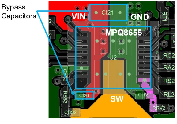
- Use Filtering Components: Add ferrite beads and bypass capacitors near IC power pins to filter out high-frequency noise. For example, a 0.1 μF capacitor can effectively suppress noise in the 100 MHz range for most digital circuits.
2. Power Distribution Issues in PCB Design
Power distribution problems can cause system instability, random reboots, or component failures in infotainment systems. These systems often require multiple voltage levels (e.g., 3.3V for digital ICs, 5V for displays, and 12V for power amplifiers), making power integrity critical. Let’s explore solutions for power distribution issues PCB:
- Ensure Adequate Power Planes: Use dedicated power planes or wide traces to distribute power with minimal voltage drop. For high-current paths, a trace width of 50 mils or more may be necessary to handle currents up to 2A without overheating.
- Place Decoupling Capacitors Correctly: Position decoupling capacitors as close as possible to the power pins of ICs. A typical setup might include a 10 μF bulk capacitor and a 0.1 μF ceramic capacitor per pin to handle transient currents.
- Avoid Voltage Drops: Calculate the expected current draw and ensure traces or planes can handle it. For example, a 12V rail supplying a 1A load over a long trace may drop to 11.5V or lower, affecting performance. Use online trace width calculators to determine the correct dimensions.
- Monitor Thermal Effects: High current can cause traces to heat up, leading to reliability issues. Use thermal vias or heat sinks near power components to dissipate heat effectively.
3. Layout Problems Leading to System Failures
PCB layout errors can introduce a range of issues, from signal integrity problems to mechanical failures. In infotainment systems, where space is limited, poor layout can be particularly problematic. For debugging PCB layout problems, focus on these areas:
- Component Placement: Place sensitive components like RF modules away from noisy areas such as switching power supplies. For example, a Wi-Fi module placed near a DC-DC converter may experience interference, reducing connection stability.
- Trace Length Matching: In high-speed designs (e.g., DDR memory or USB interfaces), mismatched trace lengths can cause timing issues. Ensure traces are matched within 5 mils for signals operating at 480 Mbps or higher to avoid data errors.
- Clearance and Creepage: Maintain proper spacing between high-voltage and low-voltage areas to prevent arcing or short circuits. For automotive applications, follow standards like IPC-2221, which recommends a minimum clearance of 0.6 mm for voltages up to 15V.
- Thermal Management: Poor layout can lead to hotspots, especially near power amplifiers or voltage regulators. Use copper pours and thermal vias to spread heat, ensuring components stay within their operating temperature range (e.g., below 85°C for most ICs).
4. Infotainment PCB Failure Analysis Techniques
When an infotainment system fails, pinpointing the root cause is crucial for quick resolution. Infotainment PCB failure analysis involves systematic testing and inspection to identify issues. Here are key techniques to follow:
- Visual Inspection: Start by checking for obvious issues like burnt components, cracked solder joints, or damaged traces. Use a magnifying glass or microscope for detailed examination, as hairline cracks in solder can be hard to spot.
- Electrical Testing: Use a multimeter to check for continuity in traces and measure voltage levels at key points. For instance, if a 3.3V rail reads only 2.8V, there may be a power delivery issue or a short circuit.
- Signal Integrity Analysis: Employ an oscilloscope to analyze signal waveforms for noise, jitter, or timing issues. A signal with excessive overshoot (e.g., exceeding 10% of the voltage level) may indicate impedance mismatch or poor termination.
- Thermal Imaging: Use a thermal camera to identify overheating components. A regulator running at 100°C when rated for 85°C maximum likely indicates a design flaw or overloading.
Preventive Measures for Reliable Infotainment PCB Design
While troubleshooting is essential, preventing issues during the design phase can save time and cost. Here are some best practices to ensure your infotainment system PCB performs reliably:
- Simulation and Testing: Use simulation tools to model signal integrity and power distribution before fabrication. Tools can predict issues like voltage drops or EMI, allowing corrections early in the design process.
- Follow Design Standards: Adhere to automotive-grade standards like AEC-Q100 for component selection and IPC-A-610 for assembly quality. These ensure the PCB can withstand harsh conditions like temperature swings from -40°C to 85°C.
- Prototype Iteratively: Build and test prototypes to catch issues before mass production. For example, a prototype may reveal that a 50 MHz clock signal causes EMI, prompting a layout change.
- Collaborate with Experts: Work with experienced PCB designers or manufacturers to review designs. Their insights can help identify potential problems, especially in complex infotainment systems.
Tools and Resources for Effective Troubleshooting
Having the right tools can make troubleshooting faster and more accurate. Here are some essential tools for diagnosing infotainment PCB issues:
- Multimeter: For measuring voltage, current, and continuity to identify power or connection issues.
- Oscilloscope: Essential for analyzing signal integrity, especially for high-speed signals above 10 MHz.
- Thermal Camera: To detect overheating components or poor thermal design.
- Logic Analyzer: Useful for debugging digital communication protocols like I2C or SPI, common in infotainment systems.
Conclusion: Building Better Infotainment PCBs
Troubleshooting common issues in infotainment system PCB design requires a systematic approach, from identifying signal noise to resolving power distribution challenges. By focusing on infotainment PCB failure analysis, debugging PCB layout problems, signal noise troubleshooting, and power distribution issues PCB, you can ensure your designs are robust and reliable. Implement the strategies discussed, use the right tools, and prioritize preventive measures to create infotainment systems that perform flawlessly even in demanding environments.
With careful planning and attention to detail, you can overcome the challenges of infotainment PCB design and deliver high-quality solutions. Keep refining your skills and stay updated with the latest design practices to stay ahead in this fast-evolving field.