 ALLPCB


Are you looking to extend the battery life of your pet tracker? Efficient power management in PCB design is the key to achieving long-lasting performance for pet tracking devices. By focusing on strategies like low power pet tracker design, battery life optimization, and pet tracker energy harvesting, you can ensure your device runs longer without frequent recharges. In this comprehensive guide, we’ll dive into actionable PCB power management techniques to help you boost battery life and create an efficient, reliable pet tracker.
Why Power Management Matters in Pet Tracking Devices
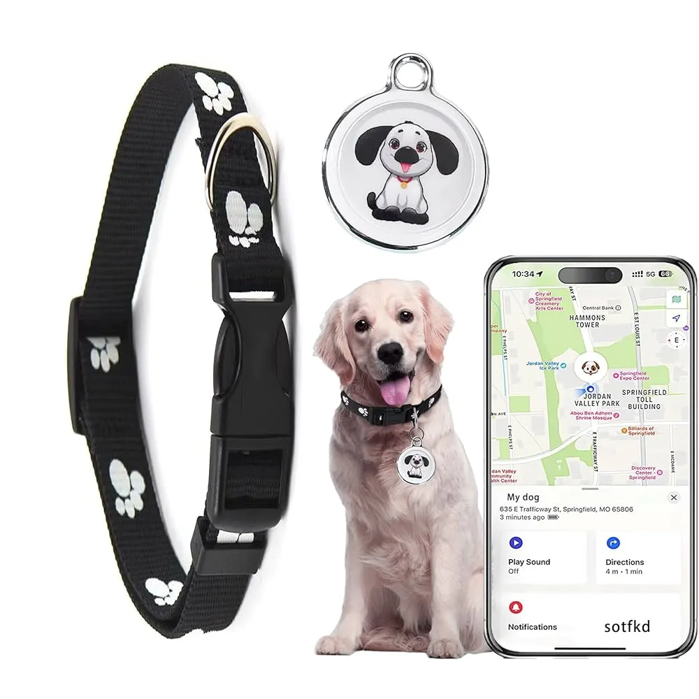
Pet trackers are essential tools for keeping our furry friends safe, providing real-time location data through GPS, cellular, or Bluetooth technologies. However, these devices often operate on small batteries, making power consumption a critical concern. High pet tracking PCB power consumption can drain batteries quickly, leaving pet owners frustrated with constant recharging or, worse, a device that fails when it’s needed most.
Efficient power management PCB design addresses this challenge by minimizing energy use while maintaining functionality. Whether you’re an engineer designing a pet tracker or a pet owner seeking to understand the technology, optimizing battery life through smart design can make a significant difference. Let’s explore the core strategies for achieving this goal.
Key Challenges in Pet Tracking PCB Power Consumption
Before diving into solutions, it’s important to understand the main factors contributing to high power consumption in pet trackers:
- GPS and Communication Modules: GPS chips and cellular or Bluetooth modules consume significant power, especially during continuous location updates or data transmission. For instance, a typical GPS module might draw 20-30 mA in active mode.
- Always-On Operation: Many pet trackers need to stay active to provide real-time tracking, preventing the device from entering deep sleep modes that save power.
- Small Battery Size: Due to size constraints, pet trackers often use compact batteries with limited capacity, such as 300-500 mAh lithium-ion cells, which can deplete quickly under heavy use.
- Environmental Factors: Temperature extremes can affect battery efficiency, reducing capacity in cold weather or accelerating drain in hot conditions.
Addressing these challenges requires a multi-faceted approach to low power pet tracker design. Let’s break down the most effective strategies.
Strategies for Efficient Power Management in PCB Design
1. Select Low-Power Components for Your PCB
The foundation of battery life optimization for pet trackers lies in choosing the right components. Opt for microcontrollers (MCUs), sensors, and communication modules specifically designed for low power consumption. For example, many modern MCUs offer power draw as low as 1-2 μA in sleep mode compared to older models that might consume 10-20 μA.
Look for GPS modules with built-in power-saving features like “tracking mode” or “duty cycling,” which reduce active time. Similarly, Bluetooth Low Energy (BLE) modules are ideal for short-range communication, consuming far less power than traditional Bluetooth—often around 0.1 mA during transmission versus 10 mA for older versions.
2. Implement Power-Saving Modes in Firmware
Firmware plays a huge role in managing pet tracking PCB power consumption. By programming the device to enter sleep or idle modes during periods of inactivity, you can drastically cut energy use. For instance, if a pet is stationary for a set time (detected via an accelerometer), the tracker can reduce GPS polling frequency from every 10 seconds to every 5 minutes, dropping power draw from 25 mA to under 5 mA during those intervals.
Additionally, use dynamic power scaling to adjust the MCU’s clock speed based on workload. Running at a lower frequency (e.g., 8 MHz instead of 48 MHz) can reduce power usage by up to 50% during non-critical tasks like data logging.
3. Optimize Communication Protocols
Data transmission is a major power hog in pet trackers. Instead of sending continuous updates, configure the device to batch data and transmit at intervals. For example, collecting location data every minute but sending it to the server every 10 minutes can save significant energy, especially for cellular-based trackers where transmission can consume 100-200 mA per burst.
Using efficient protocols like MQTT (Message Queuing Telemetry Transport) for data transfer can also minimize overhead compared to heavier protocols, reducing power draw during communication by approximately 20-30% in some setups.
4. Design for Efficient Voltage Regulation
Voltage regulators on your PCB can impact overall efficiency. Linear regulators, while simple, often waste energy as heat, with efficiency dropping to 50-60% when input and output voltages differ significantly. Switching regulators, on the other hand, can achieve 85-95% efficiency, making them ideal for pet trackers running on 3.7V lithium-ion batteries stepping down to 3.3V or lower for components.
Pay attention to quiescent current (the current a regulator draws when idle). A regulator with a quiescent current of 1 μA versus 10 μA can save noticeable power over long periods, especially in sleep mode.
5. Minimize Leakage Currents in PCB Layout
Poor PCB design can lead to leakage currents that silently drain the battery. Keep traces short and avoid running high-voltage lines near sensitive components to reduce parasitic capacitance. Use high-impedance materials for the PCB substrate to limit current leakage, which can account for 5-10 μA of unnecessary drain in poorly designed boards.
Also, ensure proper grounding to prevent noise and unintended current paths. A well-designed ground plane can reduce electromagnetic interference (EMI), which might otherwise force components to consume extra power compensating for signal issues.
Advanced Techniques: Pet Tracker Energy Harvesting
Beyond reducing consumption, pet tracker energy harvesting offers a way to supplement battery power. This involves capturing ambient energy from the environment to recharge or power the device. Here are two promising methods:
- Solar Energy Harvesting: Integrate small solar panels into the tracker’s casing. A 1 cm2 solar cell can generate 1-2 mW under direct sunlight, enough to trickle-charge a 300 mAh battery over several hours. This works best for outdoor pets with frequent sun exposure.
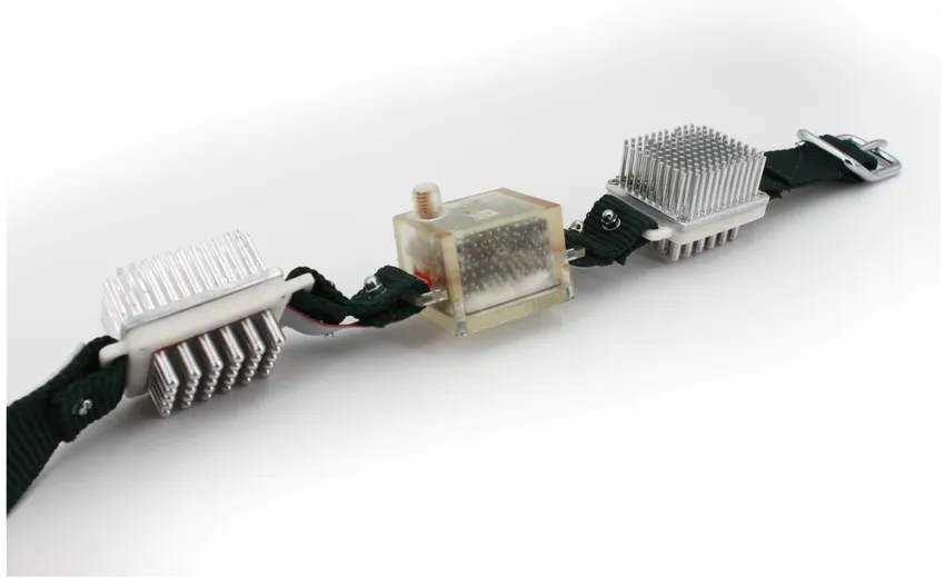
- Kinetic Energy Harvesting: Use piezoelectric materials or micro-generators to convert a pet’s movement into electrical energy. While output is small (often 0.1-0.5 mW per movement), it can offset idle power draw during active periods.
Energy harvesting requires careful PCB design to integrate storage elements like supercapacitors or tiny rechargeable batteries, along with power management ICs to handle variable input. Efficiency in these circuits is critical, as losses during conversion can negate the benefits. Aim for harvesting circuits with at least 80% efficiency to make this approach viable.
Battery Life Optimization for Pet Trackers: Practical Tips
Here are some additional tips to maximize battery life through thoughtful design and usage:
- Use Larger Batteries Where Possible: If size and weight allow, opt for a slightly larger battery (e.g., 500 mAh instead of 300 mAh) to extend runtime without changing power consumption.
- Limit LED Indicators: Bright LEDs for status updates can draw 5-10 mA. Use low-power LEDs or disable them in firmware after initial pairing to save energy.
- Optimize Antenna Design: A poorly tuned antenna for GPS or cellular signals forces the module to use more power to maintain connection. Ensure impedance matching (typically 50 ohms) to maximize signal efficiency, potentially reducing power draw by 10-15%.
- Test Under Real Conditions: Simulate pet movement and environmental factors during testing to identify power bottlenecks. A tracker might last 48 hours in a lab but only 24 hours in cold weather due to battery chemistry effects.
Balancing Power and Performance in Pet Tracker Design
While the goal is to minimize pet tracking PCB power consumption, it’s important not to compromise core functionality. A tracker that saves power by updating location only once an hour might be useless for a lost pet. Strike a balance by prioritizing features based on user needs—real-time tracking for high-risk pets versus battery life for pets that stay close to home.
Adaptive algorithms can help. For instance, increase update frequency to every 10 seconds when a pet leaves a predefined geofence, then revert to every 5 minutes when back in the safe zone. This approach can cut average power use by 30-40% compared to constant high-frequency updates, based on typical usage patterns.
Conclusion: Building a Better Pet Tracker with Smart Power Management
Boosting battery life in pet trackers is all about smart PCB design and power management. By focusing on low power pet tracker design, selecting efficient components, optimizing firmware, and exploring pet tracker energy harvesting, you can create a device that lasts longer and performs reliably. Efficient power management PCB strategies not only enhance user satisfaction but also reduce the environmental impact of frequent battery replacements.
Whether you’re designing a new tracker or improving an existing one, these techniques for battery life optimization in pet trackers offer a clear path forward. Start with small changes like component selection and firmware tweaks, then scale up to advanced solutions like energy harvesting for even greater gains. With the right approach, your pet tracker can keep pets safe without running out of juice at critical moments.


