 ALLPCB


In the fast-evolving world of RF and microwave electronics, selecting the right printed circuit board (PCB) material is critical to achieving optimal performance. Rogers PCB materials, renowned for their low dielectric loss and stable electrical properties, have become a go-to choice for high-frequency applications. But when should engineers choose Rogers materials over traditional options like PCB material FR4? In this blog, we explore the unique properties of Rogers PCB materials, their ideal use cases in RF and microwave applications, and key considerations for design and manufacturing.
Why PCB Material Matters in RF and Microwave Designs
RF and microwave circuits operate at frequencies ranging from 50 MHz to over 100 GHz, where signal integrity, impedance control, and thermal management are paramount. Unlike standard PCBs used in low-frequency applications, RF and microwave PCBs require materials that minimize signal loss, maintain consistent dielectric properties, and handle high thermal loads. Traditional FR-4 materials, while cost-effective, often fall short at frequencies above 5-10 GHz due to higher dielectric losses and less stable dielectric constants.
Rogers PCB materials, developed by Rogers Corporation, are engineered to overcome these limitations. With low loss tangents, stable dielectric constants across wide frequency ranges, and excellent thermal conductivity, Rogers laminates ensure reliable performance in demanding applications like telecommunications, aerospace, and automotive radar systems.
Key Properties of Rogers PCB Materials
To understand when to use Rogers materials, it's essential to examine their standout properties that make them ideal for RF and microwave applications. Here are the key characteristics:
Low Dielectric Loss
Rogers materials, such as RO4350B and RT/duroid 5880, have low dissipation factors (Df) ranging from 0.0009 to 0.0037, compared to FR-4's typical Df of 0.02. This minimizes signal attenuation, ensuring high signal integrity in applications like antennas and power amplifiers. For example, at 10 GHz, Rogers RO4350B exhibits a loss tangent of 0.0037, resulting in less than 0.5 dB signal loss per inch, whereas FR-4 can exceed 1 dB under similar conditions.
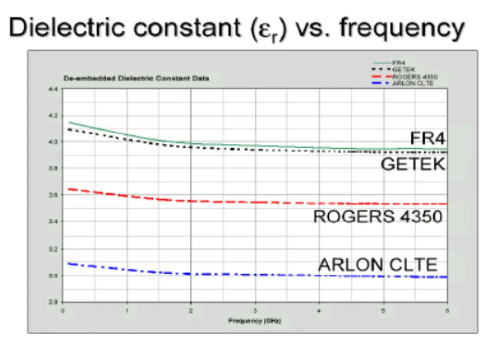
Stable Dielectric Constant (Dk)
A stable dielectric constant is crucial for predictable impedance control. Rogers materials offer Dk values ranging from 2.2 (RT/duroid 5880) to 10.2 (RO3010), with tight tolerances (±0.05 for RO4350B). This stability across frequencies up to 77 GHz ensures consistent performance in high-frequency circuits, unlike FR-4, which can vary significantly above 1 GHz.
High Thermal Conductivity
Rogers laminates, such as RO4003C, provide thermal conductivity of 0.6-0.8 W/mK, compared to FR-4's 0.1-0.5 W/mK. This enables efficient heat dissipation in high-power RF applications, such as base station amplifiers, where PCB thermal management prevents circuit failure.
Low Moisture Absorption
With moisture absorption rates as low as 0.1%, Rogers materials like RO3003 maintain electrical performance in humid environments, making them suitable for outdoor applications like satellite communications. FR-4, with up to 0.5% moisture absorption, is less reliable under similar conditions.
Dimensional Stability
Rogers materials have a low coefficient of thermal expansion (CTE), closely matching copper (approximately 18 ppm/°C). This ensures dimensional stability across temperature ranges, critical for multilayer designs in aerospace and defense applications.
Popular Rogers PCB Materials for RF and Microwave Applications
Rogers Corporation offers a diverse portfolio of laminates, each tailored to specific RF and microwave needs. Below are some of the most widely used materials and their applications:
RO4350B
- Dielectric Constant: 3.48 ± 0.05
- Dissipation Factor: 0.0037 at 10 GHz
- Applications: High-frequency power amplifiers, antenna arrays, and 5G base stations
- Why Choose It: RO4350B balances cost and performance, offering low loss and compatibility with standard FR-4 processing methods, reducing manufacturing complexity.
RO4003C
- Dielectric Constant: 3.55
- Dissipation Factor: 0.0027 at 10 GHz
- Applications: Microwave point-to-point links, RFID tags, and automotive sensors
- Why Choose It: This hydrocarbon ceramic laminate provides excellent electrical performance and ease of fabrication, making it cost-effective for commercial applications.
RT/duroid 5880
- Dielectric Constant: 2.2
- Dissipation Factor: 0.0009 at 10 GHz
- Applications: mmWave antennas, radar systems, and satellite communications
- Why Choose It: Its ultra-low loss and lightweight PTFE composite make it ideal for broadband and high-frequency applications up to mmWave bands.
RO3003
- Dielectric Constant: 3.0
- Dissipation Factor: 0.0013 at 10 GHz
- Applications: 77 GHz automotive radar, 6G wireless systems
- Why Choose It: Offers exceptional dielectric stability and low loss, perfect for high-frequency radar and wireless applications.
When to Choose Rogers PCB Materials
Rogers materials are not always necessary, as FR-4 can suffice for low- to medium-frequency applications below 5 GHz. However, engineers should opt for Rogers laminates in the following scenarios:
High-Frequency Designs (>5 GHz)
At frequencies above 5-10 GHz, FR-4's higher dielectric loss (Df ~0.02) causes significant signal attenuation, making Rogers materials essential. For instance, in 5G systems operating at 28 GHz, RO4350B's low loss ensures minimal signal degradation over long traces.
Impedance-Critical Applications
RF circuits require precise impedance control (e.g., 50Ω or 75Ω) to prevent signal reflections. Rogers' tight Dk tolerances (±0.05) enable accurate trace width calculations, ensuring consistent impedance. For example, a microstrip line on RO4003C with a Dk of 3.55 can maintain 50Ω impedance with a trace width of 0.3 mm at 10 GHz.
High-Power RF Circuits
High-power applications, such as base station amplifiers, generate significant heat. Rogers' superior thermal conductivity (e.g., 0.7 W/mK for RO4350B) dissipates heat effectively, preventing performance degradation.
Harsh Environmental Conditions
In applications like satellite systems or outdoor antennas, low moisture absorption and thermal stability are critical. Rogers materials, with moisture absorption as low as 0.1%, outperform FR-4 in humid or high-temperature environments.
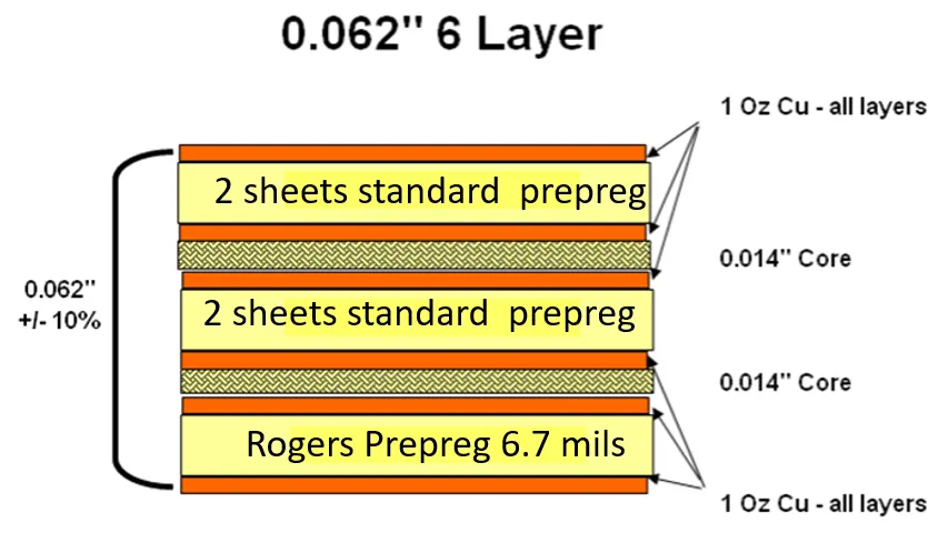
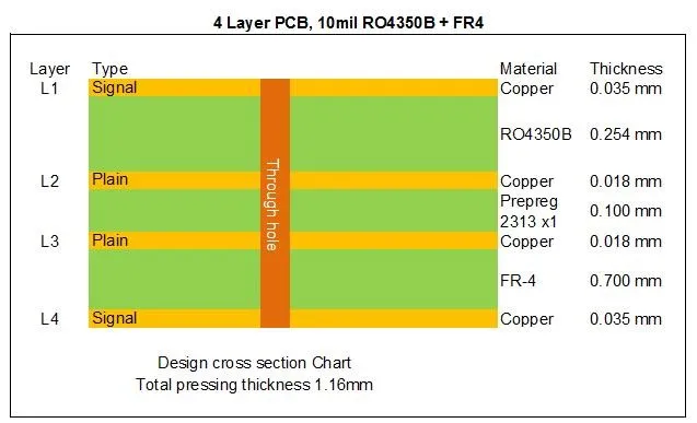
Multilayer and Hybrid Designs
For complex multilayer PCBs, Rogers materials can be combined with FR-4 to balance cost and performance. A hybrid stackup with Rogers RO4350B on signal layers and FR-4 on power/ground layers reduces signal loss while keeping costs manageable.
Design and Manufacturing Considerations for Rogers PCBs
While Rogers materials offer superior performance, they require careful handling during design and manufacturing to maximize their benefits. Here are key considerations:
Material Handling
Rogers laminates, especially PTFE-based ones like RT/duroid 5880, are softer and more brittle than FR-4. Use gentle handling to avoid surface damage or contamination, which can affect dielectric properties.
Drilling and Routing
To prevent overheating and maintain hole quality, use lower drill speeds and feed rates compared to FR-4. For example, a drill speed of 30,000 RPM with a feed rate of 50 inches/min is suitable for RO4350B.
Lamination
Follow Rogers' recommended lamination profiles to ensure proper bonding. For RO4003C, a lamination temperature of 370°F and pressure of 300 psi ensure optimal adhesion without degrading material properties.
Etching
Adjust PCB etching process to account for Rogers' chemical properties. Use milder etchants and shorter exposure times to prevent over-etching, which can compromise trace integrity.
Impedance Control
Calculate trace widths and spacing based on the specific Dk of the chosen Rogers material. Tools like Rogers' MWI (Microwave Impedance) calculator can help determine precise dimensions for 50Ω or 75Ω impedance.
Cost vs. Performance Trade-Offs
Rogers PCB materials are more expensive than FR-4, with costs ranging from $50-$100 for a 10cm x 10cm board compared to $10-$20 for FR-4. However, their performance benefits often justify the investment in high-frequency applications. For cost-sensitive projects, consider hybrid stackups or lower-cost Rogers materials like AD250C, which offers a Dk of 2.5 and competitive performance at a reduced price.
To optimize costs, evaluate the frequency range, loss requirements, and thermal demands of your design. For applications below 5 GHz with moderate performance needs, FR-4 may suffice. Above 5 GHz or in high-reliability systems, Rogers materials deliver unmatched value.
How ALLPCB Supports Rogers PCB Projects
For engineers working on RF and microwave projects, ALLPCB offers advanced manufacturing capabilities tailored to Rogers PCB materials. Our quick-turn prototyping services deliver high-quality Rogers-based PCBs in as little as 24-48 hours, enabling rapid design iterations. With global logistics and partnerships with leading material suppliers, we ensure access to authentic Rogers laminates like RO4350B and RO4003C. Our state-of-the-art facilities support precise impedance control, multilayer stackups, and hybrid designs, helping engineers bring high-performance RF circuits to market efficiently.
Conclusion: Making the Right Choice for RF and Microwave PCBs
Rogers PCB materials are the gold standard for RF and microwave applications, offering low dielectric loss, stable Dk, and excellent thermal management. Engineers should choose Rogers laminates for high-frequency designs above 5 GHz, impedance-critical circuits, high-power applications, or harsh environmental conditions. By understanding the properties of materials like RO4350B, RO4003C, and RT/duroid 5880, and following best practices in design and manufacturing, you can unlock the full potential of your RF and microwave projects.
At ALLPCB, we're committed to supporting engineers with the tools and expertise needed to succeed. Whether you're prototyping a 5G antenna or designing a radar system, Rogers PCB materials-paired with our manufacturing capabilities-can help you achieve reliable, high-performance results.


