ALLPCB


If you're an electrical engineer working on a PCB fabrication project, choosing the right FR-4 material is critical for ensuring performance, reliability, and cost-effectiveness. FR-4, a widely used glass-reinforced epoxy laminate, is known for its balance of strength, electrical insulation, and flame resistance. But with variations in thickness, thermal properties, and compliance standards like UL 94V-0, how do you select the best FR-4 material for your specific needs? In this guide, we'll dive deep into FR-4 PCB material properties, thickness for impedance control, cost comparisons with high-frequency materials, suitability for high-temperature applications, and the importance of UL 94V-0 ratings. Let's explore everything you need to know to make an informed decision.
What is FR-4 Material and Why Does It Matter for PCB Fabrication?
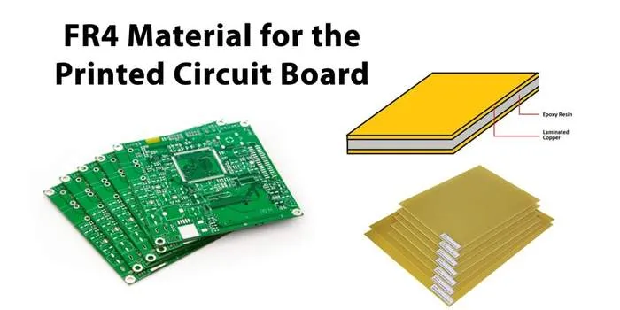
FR-4 is a composite material made of woven fiberglass cloth and an epoxy resin binder, designed to be flame retardant (hence the "FR" designation). Introduced by NEMA in 1968, FR-4 has become the go-to material for printed circuit boards (PCBs) due to its excellent mechanical strength, low water absorption, and electrical insulation properties. Whether you're designing a simple single-layer PCB or a complex multilayer board, FR-4 offers versatility for a wide range of applications.
For engineers, understanding FR-4 is essential because it directly impacts the performance and durability of your PCB. Factors like dielectric constant (Dk), thermal conductivity, and compliance with safety standards can make or break your project. In the sections below, we’ll break down the key considerations to help you choose the right FR-4 material.
FR-4 PCB Material Properties: What You Need to Know
Before selecting an FR-4 material, it's important to understand its core properties. These characteristics determine how the material will perform under various conditions in your PCB design. Here are the key FR-4 material properties every engineer should consider:
- Dielectric Constant (Dk): FR-4 typically has a Dk value of around 4.5 at 1 MHz, which affects signal speed and integrity. A higher Dk slows down signal transmission, which may be a concern for high-frequency designs.
- Dissipation Factor (Df): With a Df of 0.01–0.025, FR-4 exhibits moderate signal loss. This makes it suitable for low to medium-frequency applications but less ideal for high-speed circuits.
- Thermal Conductivity: FR-4 has a thermal conductivity of about 0.3 W/m·K, which is relatively low. This means it's not the best choice for dissipating heat in high-power applications without additional thermal management solutions.
- Glass Transition Temperature (Tg): Standard FR-4 has a Tg of 130–140°C, though high-Tg variants can reach 170–180°C. This determines the material’s ability to withstand heat during soldering or operation.
- Flame Retardancy: FR-4 is inherently flame retardant, and most variants meet the UL 94V-0 standard, ensuring the material self-extinguishes in case of fire.
- Mechanical Strength: With a tensile strength of approximately 310 MPa, FR-4 provides robust support for components, even in harsh environments.
These properties make FR-4 a reliable and cost-effective choice for many projects. However, for specialized applications like high-frequency or high-temperature designs, you may need to consider variants of FR-4 or alternative materials, which we'll discuss later.
FR-4 Thickness for Impedance Control: Getting It Right
Impedance control is a critical factor in PCB design, especially for high-speed digital and RF applications. The thickness of the FR-4 material plays a significant role in achieving the desired characteristic impedance, typically 50 ohms for most RF designs. Here's how FR-4 thickness impacts impedance and what engineers should consider:
The characteristic impedance of a trace depends on the dielectric thickness (distance between the trace and the ground plane), the dielectric constant of the material, and the trace width. For FR-4 with a Dk of 4.5, a common thickness for standard PCBs is 1.6 mm (0.062 inches). However, for precise impedance control, thinner or thicker FR-4 substrates may be required. For example:
- A thinner FR-4 substrate (e.g., 0.8 mm) brings the trace closer to the ground plane, reducing impedance. This may require narrower traces to achieve the target impedance.
- A thicker substrate (e.g., 2.4 mm) increases the distance, raising impedance, which may necessitate wider traces.
For multilayer boards, engineers often use core and prepreg layers of varying thicknesses to fine-tune impedance. Standard FR-4 thicknesses range from 0.2 mm to 3.2 mm, and working with your PCB manufacturer to select the right stack-up is crucial. Tools like impedance calculators or simulation software (e.g., Altium Designer or ANSYS) can help you determine the optimal FR-4 thickness for your design.
As a practical tip, always account for manufacturing tolerances. FR-4 thickness can vary by ±10%, which may affect impedance if not considered during design. Requesting controlled dielectric materials from your supplier can minimize variations.
Cost Comparison: FR-4 vs. High-Frequency Materials
One of the biggest advantages of FR-4 is its cost-effectiveness. However, for high-frequency applications (above 1 GHz), FR-4 may not perform as well as specialized materials like Rogers or PTFE-based laminates. Let's compare the costs and performance to help you decide which material suits your budget and project requirements.
- FR-4 Cost: FR-4 is one of the most affordable PCB materials, with prices typically ranging from $0.50 to $2.00 per square foot for standard thicknesses (e.g., 1.6 mm). This makes it ideal for low to medium-frequency applications and mass production.
- High-Frequency Materials Cost: Materials like Rogers 4350B or PTFE (e.g., Teflon) can cost $5 to $15 per square foot or more, depending on the grade and thickness. These materials offer lower dielectric constants (Dk of 2.1–3.5) and dissipation factors (Df of 0.0002–0.001), ensuring better signal integrity at high frequencies.
- Performance Trade-Offs: While FR-4 struggles with signal loss and slower signal speeds at frequencies above 1 GHz, high-frequency materials are designed to minimize these issues. However, for many applications below 1 GHz, such as consumer electronics or industrial controls, FR-4 provides sufficient performance at a fraction of the cost.
For engineers on a budget, consider using hybrid stack-ups that combine FR-4 with high-frequency materials only on critical layers. This approach balances cost and performance, allowing you to save money without compromising on signal integrity where it matters most.
FR-4 for High-Temperature Applications: Is It Suitable?
High-temperature applications, such as automotive electronics or industrial equipment, require PCB materials that can withstand elevated temperatures without degrading. Standard FR-4 has a glass transition temperature (Tg) of 130–140°C, which is sufficient for many applications but may not be enough for extreme conditions.
For high-temperature environments, consider high-Tg FR-4 variants with Tg values of 170–180°C. These materials are better suited for lead-free soldering processes, which often require temperatures above 260°C during reflow. High-Tg FR-4 maintains its mechanical and electrical properties at higher temperatures, reducing the risk of delamination or warping.
However, FR-4, even high-Tg variants, has limitations. Its thermal conductivity of 0.3 W/m·K means it doesn’t dissipate heat well. For applications with significant heat generation, such as power electronics, you may need to pair FR-4 with heat sinks or consider alternative substrates like aluminum-backed PCBs, which offer thermal conductivity up to 1–2 W/m·K or higher.
As a real-world example, in automotive engine control units (ECUs), high-Tg FR-4 is often used to handle temperatures up to 150°C. Engineers supplement this with thermal vias and copper pours to manage heat effectively. Always check the operating temperature range of your components and ensure the FR-4 variant you choose can handle the thermal stress of your application.

Understanding UL 94V-0 Rated FR-4: Safety First
Safety is a top priority in PCB design, especially for applications where fire hazards are a concern. The UL 94V-0 rating is a flammability standard set by Underwriters Laboratories, and most FR-4 materials are designed to meet this criterion. But what does UL 94V-0 mean, and why is it important?
UL 94V-0 indicates that the material is highly flame retardant and will self-extinguish within 10 seconds after the flame source is removed during vertical burn testing. This rating ensures that FR-4 won't sustain a fire, making it safe for use in consumer electronics, industrial equipment, and other applications where electrical faults could ignite a fire.
When selecting FR-4, always confirm with your supplier that the material is UL 94V-0 certified. This certification is often listed on the material datasheet. For critical applications, such as medical devices or aerospace electronics, you may also need to comply with additional safety standards, but UL 94V-0 is a baseline for flame resistance.
How to Choose the Right FR-4 Material for Your Project
Now that we've covered the key aspects of FR-4, let's summarize how to choose the right material for your PCB fabrication project. Follow these steps to make an informed decision:
- Define Your Application Requirements: Determine the frequency range, temperature conditions, and safety standards for your project. This will help you decide if standard FR-4, high-Tg FR-4, or a hybrid solution is needed.
- Calculate Impedance Needs: Use simulation tools to select the appropriate FR-4 thickness for impedance control, especially for high-speed designs.
- Evaluate Thermal Management: Assess the heat generation in your design and choose high-Tg FR-4 or additional cooling solutions if operating temperatures exceed 130°C.
- Consider Cost Constraints: Balance performance and budget by comparing FR-4 with high-frequency materials. Use hybrid stack-ups if high-frequency performance is only needed on specific layers.
- Verify Safety Compliance: Ensure the FR-4 material is UL 94V-0 rated to meet fire safety requirements.
- Collaborate with Your Manufacturer: Work closely with your PCB supplier to confirm material availability, tolerances, and stack-up recommendations.
By following these steps, you can confidently select an FR-4 material that meets your technical and budgetary needs. Remember, the right material choice can save you from costly redesigns or performance issues down the line.
Conclusion: Making the Best Choice for Your PCB Design
Choosing the right FR-4 material for your PCB fabrication project doesn't have to be complicated. By understanding FR-4 PCB material properties, optimizing thickness for impedance control, comparing costs with high-frequency materials, evaluating suitability for high-temperature applications, and ensuring UL 94V-0 compliance, you can make a decision that ensures reliability and performance. FR-4 remains a versatile, cost-effective option for most applications, and with the right variant or design considerations, it can meet even demanding requirements.
As an electrical engineer, your goal is to balance performance, safety, and cost. Use the insights and practical tips from this guide to select the best FR-4 material for your next project. Have questions or specific challenges with FR-4 in your design? Drop a comment below or reach out to your PCB manufacturer for tailored advice. Let's build better electronics together!