ALLPCB


If you're looking to repair an ECU (Engine Control Unit) PCB (Printed Circuit Board) on your own, having the right tools is crucial. Whether you're a hobbyist or a professional, a well-equipped DIY PCB repair kit can save you time and money. In this guide, we'll cover the essential tools for ECU PCB repair, including a soldering iron for PCB repair, a multimeter for electronics, and desoldering tools, to help you tackle common issues with confidence.
This blog post will dive deep into each tool, explaining its purpose, how to use it, and why it’s vital for successful repairs. We'll also provide practical tips to build your DIY PCB repair kit and ensure you're prepared for any challenge. Let's get started!
Why ECU PCB Repair Matters
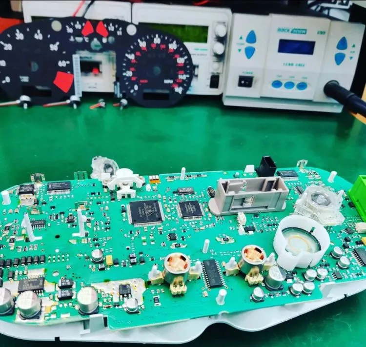
The ECU is the brain of a vehicle, controlling critical functions like fuel injection, ignition timing, and emissions. When the PCB inside the ECU fails, it can lead to performance issues or even render the car undrivable. Repairing an ECU PCB yourself can be a cost-effective alternative to replacement, which often costs hundreds or thousands of dollars. However, without the proper ECU PCB repair tools, you risk further damage or incomplete fixes.
By assembling a DIY PCB repair kit with the right equipment, you can address common problems like cracked solder joints, damaged traces, or faulty components. This guide will walk you through the must-have tools to make these repairs possible.
Building Your DIY PCB Repair Kit: The Essentials
Before diving into specific tools, let’s outline what a comprehensive DIY PCB repair kit should include. Each item plays a unique role in diagnosing, repairing, and testing an ECU PCB. Below, we’ll break down the key tools, focusing on their purpose and practical use.
1. Soldering Iron for PCB Repair
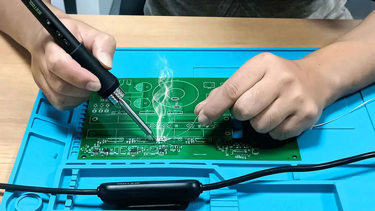
A soldering iron is the cornerstone of any PCB repair job. It’s used to melt solder—a metal alloy that creates electrical connections between components and the board. For ECU PCB repair, you need a soldering iron with precise temperature control to avoid overheating sensitive components.
Key Features to Look For:
- Temperature Control: Look for a soldering iron with adjustable temperature settings, ideally between 300°C to 400°C (572°F to 752°F), to handle various solder types and components.
- Fine Tip: A fine tip (0.5mm to 1mm) is essential for working on small, densely packed ECU PCBs.
- Wattage: A 25W to 40W soldering iron is sufficient for most PCB work, providing enough heat without risking damage.
How to Use It: Heat the soldering iron to the appropriate temperature, apply flux to the joint for better solder flow, and touch the tip to the joint while feeding solder wire. Be quick to avoid overheating components—aim for 2-3 seconds per joint.
Tip: Always clean the soldering iron tip with a damp sponge or tip cleaner after each use to prevent oxidation and ensure clean connections.
2. Multimeter for Electronics
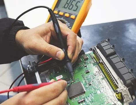
A multimeter is an indispensable tool for diagnosing issues on an ECU PCB. It measures voltage, current, and resistance, helping you identify faults like short circuits, open circuits, or failed components.
Key Features to Look For:
- Digital Display: A digital multimeter (DMM) offers precise readings compared to analog models.
- Continuity Test: This feature beeps when a circuit is complete, making it easy to check for broken traces or connections.
- Range: Ensure it can measure DC voltage up to at least 20V, as most automotive ECUs operate at 12V systems.
How to Use It: Set the multimeter to the appropriate mode (e.g., DC voltage or continuity). For voltage testing, touch the probes to the positive and negative points of a circuit—typical ECU circuits should read around 5V or 12V for logic and power lines. For continuity, test between two points to see if there’s a connection; no beep means a broken trace.
Tip: Always double-check your probe placement to avoid shorting components. Incorrect readings, like a voltage drop below 4.5V on a 5V line, often indicate a failing regulator or capacitor.
3. Desoldering Tools
Desoldering tools are critical for removing old or damaged components from an ECU PCB without causing harm to the board. These tools help you extract solder from joints so you can replace faulty parts like resistors, capacitors, or IC chips.
Types of Desoldering Tools:
- Desoldering Pump (Solder Sucker): A manual tool that uses suction to remove molten solder. It’s affordable and ideal for beginners.
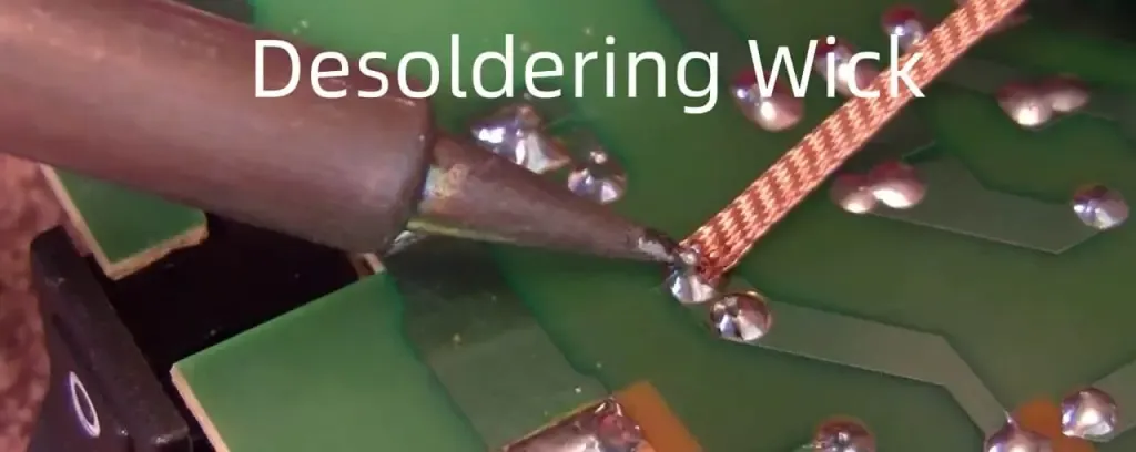
- Desoldering Wick (Braid): A braided copper wire that absorbs solder when heated. It’s great for cleaning up small amounts of solder or hard-to-reach areas.
- Desoldering Station: A more advanced option with a heated tip and built-in vacuum for professional-grade removal. Best for frequent repairs.
How to Use Them: For a desoldering pump, heat the solder joint with your soldering iron, then quickly place the pump’s nozzle over the molten solder and press the trigger to suck it up. With a desoldering wick, place the braid over the joint, heat it with the iron, and let the solder wick into the braid. Be cautious not to overheat pads, as ECU PCBs often have delicate traces that can lift off.
Tip: Use flux with desoldering wick to improve solder absorption and reduce the risk of damaging the board.
4. Flux and Solder Wire
Flux is a chemical agent that cleans and prepares surfaces for soldering by removing oxidation, ensuring strong, reliable joints. Solder wire is the material you melt to create electrical connections.
Key Features to Look For:
- Flux: Choose a no-clean flux for convenience, as it leaves minimal residue. Rosin-based flux is also common for electronics.
- Solder Wire: Opt for lead-free solder with a diameter of 0.6mm to 1mm for fine PCB work. A 63/37 tin-lead mix can be used if regulations permit, as it melts at a lower temperature (around 183°C or 361°F).
How to Use Them: Apply flux to the joint before soldering or desoldering to improve flow and adhesion. Feed solder wire sparingly to avoid blobs that can cause shorts.
Tip: Store solder wire in a cool, dry place to prevent oxidation, which can weaken joints.
5. Precision Screwdrivers and Tweezers
ECU units often need to be disassembled before you can access the PCB. Precision screwdrivers help remove tiny screws, while tweezers are perfect for handling small components like surface-mount resistors or capacitors.
Key Features to Look For:
- Screwdrivers: A set with multiple heads (Phillips, flathead, Torx) in small sizes (e.g., 1.5mm to 3mm) works best.
- Tweezers: Anti-static, fine-tip tweezers prevent damage to components and protect against static discharge.
How to Use Them: Use screwdrivers to carefully open the ECU casing without stripping screws. Tweezers are ideal for placing or removing tiny parts during soldering.
Tip: Work on an anti-static mat or wear an anti-static wrist strap to avoid damaging sensitive ECU components with electrostatic discharge (ESD).
6. Magnifying Glass or Microscope
ECU PCBs often have tiny components and traces that are hard to see with the naked eye. A magnifying glass or a digital microscope helps you inspect solder joints, identify cracks, or read component markings.
Key Features to Look For:
- Magnification: A 5x to 10x magnifying glass is sufficient for basic work. For detailed inspection, a digital microscope with 20x to 50x zoom and a screen is ideal.
- Lighting: Built-in LED lighting improves visibility on dark boards.
How to Use It: Inspect the PCB before and after repair to spot issues like cold solder joints (dull, cracked connections) or lifted pads.
Tip: Pair your magnifying tool with a steady work surface to keep the PCB stable during inspection.
Additional Tools for Advanced ECU PCB Repair
Beyond the basics, a few advanced tools can make complex repairs easier, especially for professionals or frequent DIYers.
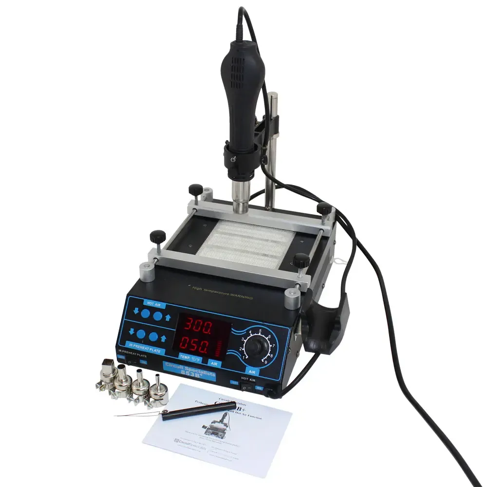
- Hot Air Rework Station: Uses controlled hot air to remove or reflow surface-mount components. Ideal for replacing IC chips on ECU PCBs. Look for models with adjustable temperature (100°C to 500°C or 212°F to 932°F) and airflow settings.
- PCB Holder or Third Hand: Holds the board steady while you work, often with adjustable arms and magnifying lenses.
- Cleaning Supplies: Isopropyl alcohol (90% or higher) and a soft brush remove flux residue and dirt after soldering.
Step-by-Step Guide to ECU PCB Repair with Your DIY Kit
Now that you have your DIY PCB repair kit ready, let’s walk through a basic repair process for an ECU PCB.
- Diagnose the Issue: Use a multimeter for electronics to test for power issues, shorts, or broken traces. Look for voltage drops (e.g., below 4.5V on a 5V line) or no continuity where there should be a connection.
- Disassemble the ECU: Use precision screwdrivers to open the unit and access the PCB. Handle with care to avoid static damage.
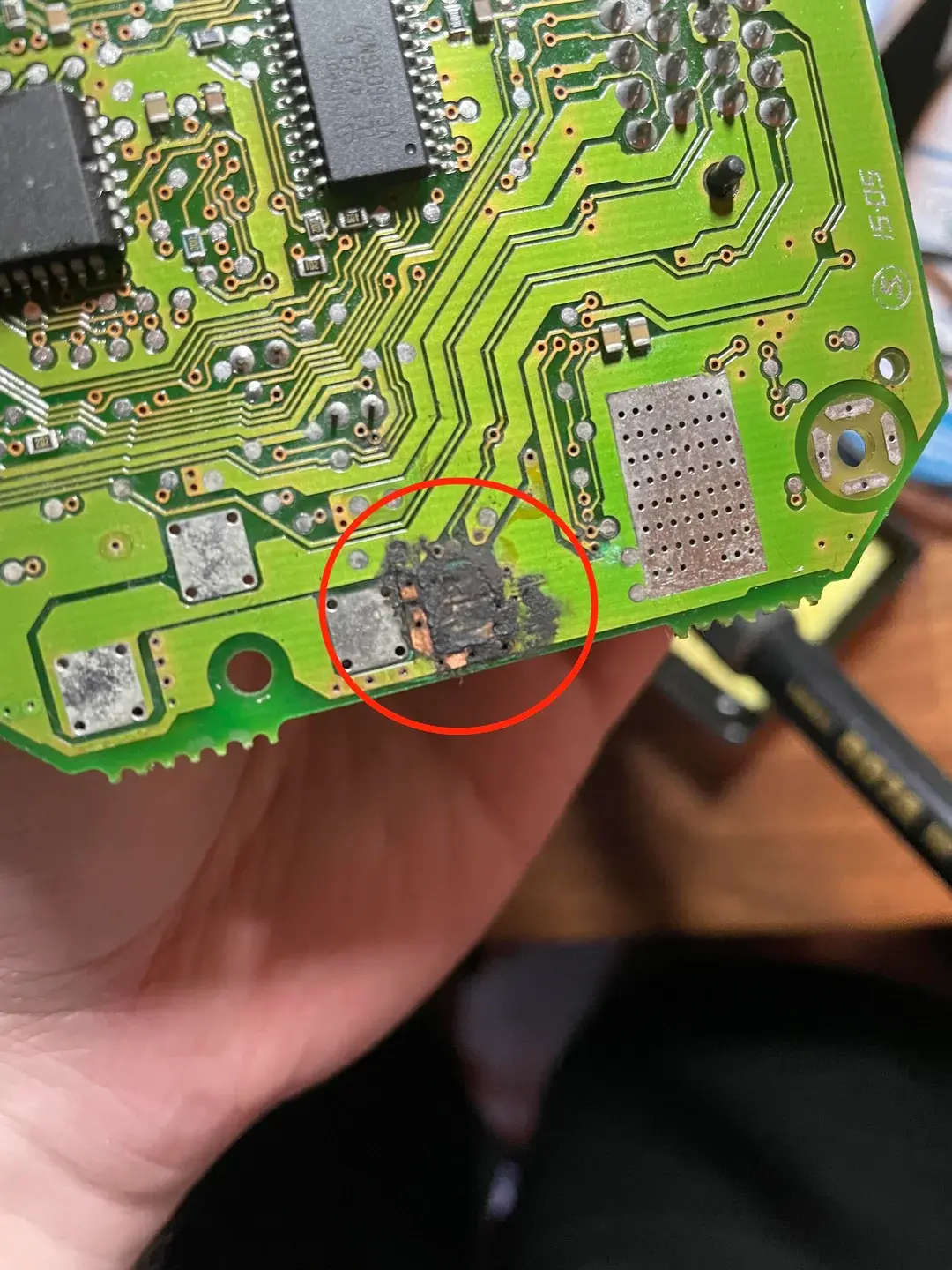
- Inspect the Board: Use a magnifying glass to check for visible damage like burnt components or cracked solder joints.
- Remove Faulty Components: Use desoldering tools to extract damaged parts. Apply flux and heat the joints, then use a pump or wick to clear solder.
- Install New Components: Place the replacement part, apply flux, and use a soldering iron for PCB repair to create clean joints.
- Clean and Test: Clean the board with isopropyl alcohol, then use a multimeter to verify connections and voltages (e.g., 5V for logic circuits).
- Reassemble and Install: Put the ECU back together and test it in the vehicle for proper operation.
Tip: Work in a well-ventilated area when soldering to avoid inhaling fumes, and always wear safety glasses to protect against solder splatter.
Safety Tips for ECU PCB Repair
Repairing an ECU PCB involves heat, chemicals, and delicate electronics, so safety is paramount.
- Work on a non-conductive, heat-resistant surface to prevent shorts or burns.
- Use anti-static protection to avoid damaging sensitive components with ESD.
- Keep soldering tools away from flammable materials, as tips can reach over 300°C (572°F).
- Wash hands after handling solder or flux to avoid exposure to harmful substances.
Conclusion: Empower Your Repairs with the Right ECU PCB Repair Tools
Repairing an ECU PCB can be a rewarding and cost-saving project if you have the right tools in your DIY PCB repair kit. From a reliable soldering iron for PCB repair to a trusty multimeter for electronics and effective desoldering tools, each piece of equipment plays a vital role in diagnosing and fixing issues. By investing in quality ECU PCB repair tools and following safe practices, you can tackle common problems like solder joint failures or component damage with confidence.
Start small by practicing on scrap boards to build your skills, and gradually take on more complex repairs. With the tools and tips outlined in this guide, you’re well on your way to mastering ECU PCB repair. Keep your kit organized, stay patient, and enjoy the process of bringing electronics back to life!