 ALLPCB


Introduction
Surface mount technology (SMT) has transformed electronics manufacturing by enabling higher component densities and improved performance on printed circuit boards (PCBs). Central to the SMT assembly process is solder paste, a critical material that facilitates reliable electrical and mechanical connections between components and the board. SMT solder paste bridges the gap from bare PCB preparation to fully assembled modules through precise application and controlled reflow. Engineers must understand its behavior to minimize defects like bridging or insufficient wetting. This article explores solder paste from deposition to reflow, offering practical insights for optimizing yields. Key stages include printing, placement, and thermal processing, each influenced by material properties and process controls.

What Is SMT Solder Paste and Why It Matters
SMT solder paste is a homogeneous mixture of microscopic solder powder particles suspended in a flux medium, designed specifically for surface mount applications. It serves multiple functions: holding components in place during placement, removing oxides during heating, and forming robust solder joints upon solidification. Without proper solder paste, the SMT assembly process risks failures such as open joints or tombstoning, which compromise reliability in high-volume production. Its importance lies in achieving consistent volume transfer and reflow characteristics, directly impacting assembly yields and long-term product performance. Engineers rely on it for fine-pitch components where precision is paramount. In essence, solder paste dictates the quality of interconnections in modern electronics.
Solder Paste Composition
Solder paste composition typically consists of 85 to 92 percent by weight of solder alloy powder, with the remainder being flux vehicle. Common alloys include tin-silver-copper variants that meet requirements outlined in IPC J-STD-006 for electronic-grade materials. The powder particles are spherical and classified by size, influencing printability and reflow behavior; finer types suit smaller apertures while coarser ones provide better stability. Flux components include activators for oxide removal, rosins or synthetic equivalents for protection, solvents for viscosity control, and additives to prevent slumping. This balance ensures the paste remains stable during storage and application yet activates effectively in reflow soldering. Variations in metal loading or flux chemistry allow tailoring to specific process windows, but consistency is key to repeatable results.
The alloy in solder paste must conform to purity levels specified in standards to avoid issues like brittleness or electromigration. Flux types range from no-clean formulations that minimize post-reflow residues to water-soluble ones requiring thorough cleaning. Particle size distribution affects rheology, with tighter distributions reducing variability in deposit height. Engineers troubleshoot composition mismatches by examining reflow defects, such as excessive voids from poor flux activation. Proper formulation prevents phase separation during printing or prolonged shelf life. Overall, understanding solder paste composition enables proactive process adjustments.
Related Reading: Choosing the Right Solder Paste for Your Stencil Printer Projects
The Solder Paste Application Process
The solder paste application process begins with stencil printing, where paste is forced through apertures onto PCB pads using a squeegee blade. Stencil design guidelines, such as those in IPC-7525, recommend aperture aspect ratios and wall thicknesses to ensure clean release and uniform deposits. Key parameters include print speed, pressure, snap-off distance, and gasketing to avoid paste starvation or bridging between pads. Boards must be clean and flat-coped to promote adhesion, with automated inspection verifying volume and shape post-print. This stage sets the foundation for the entire SMT assembly process, as inconsistent deposits propagate defects downstream. Troubleshooting often reveals issues like stencil wear causing scooped or insufficient paste.

After printing, the PCB advances to component placement, where high-speed pick-and-place machines position devices into the tacky paste. Self-alignment occurs as surface tension pulls components onto pads during reflow, but precise placement minimizes offsets. Paste height typically measures 75 to 125 percent of pad thickness, adjustable via stencil foils. Environmental controls, like temperature and humidity between 23 and 27 degrees Celsius and 40 to 60 percent relative humidity, prevent drying or separation. Engineers monitor shear thinning behavior to optimize rheology for high-speed lines. Deviations here demand recipe tweaks, such as viscosity adjustments.
Reflow Soldering in SMT Assembly
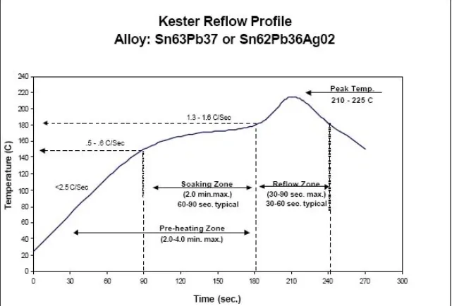
Reflow soldering melts the solder paste deposits to form intermetallic bonds between component terminations, pads, and alloy particles. The process follows a thermal profile with preheat, soak, reflow, and cooling zones in a conveyor oven. Preheat ramps gently to evaporate solvents and activate flux without spattering, typically reaching 150 degrees Celsius. Soak homogenizes temperatures across the assembly, promoting even oxide removal. Peak reflow exceeds the alloy liquidus by 20 to 40 degrees Celsius for complete coalescence, followed by controlled cooling to refine microstructure and avoid thermal shock. Profiles align with IPC/JEDEC J-STD-020 classifications for moisture-sensitive devices.
Related Reading: A Beginner's Guide to Reflow Soldering
Monitoring involves thermocouples on test boards to validate time above liquidus and peak temperatures. Nitrogen atmospheres reduce oxidation, enhancing wetting on fine features. Post-reflow inspection checks fillet formation and voiding per IPC-A-610 criteria. Troubleshooting reflow issues, like hot spots from uneven conveyor loading, requires profile tuning. Belt speed and zone settings balance throughput with quality. Ultimately, reflow transforms viscous paste into durable joints central to surface mount technology reliability.
Best Practices for Solder Paste Handling and Process Optimization
Store SMT solder paste refrigerated at 2 to 10 degrees Celsius to extend shelf life up to six months, allowing full thaw at room temperature before use to avoid condensation. Pre-condition jars by rolling to homogenize, then dispense via auger pumps for consistent volume. Implement automated solder paste inspection (SPI) after printing to quantify height, area, and offset, rejecting boards outside tolerances. Clean stencils ultrasonically with approved solvents to maintain release efficiency. For reflow, validate profiles with real-time profiling tools, adjusting for board thickness and component density. These steps, grounded in practical experience, boost first-pass yields above 99 percent.
Troubleshoot common defects systematically: bridging from excess paste signals high squeegee pressure or worn stencils, resolved by reducing speed or polishing. Insufficient solder volume or dewetting points to flux incompatibility or pad contamination, addressed by surface activation. Tombstoning arises from rapid heating gradients, mitigated by slower preheat ramps. Voiding over 25 percent in BGAs may indicate trapped flux gases, improved via ramp-to-peak optimizations. Track viscosity via slump and sag tests periodically. Document process windows to scale from prototypes to production.
In high-mix environments, qualify pastes for multiple alloys and flux strengths to minimize changeover times. Train operators on handling to prevent contamination from tools or gloves. Integrate data analytics from SPI and AOI for predictive maintenance. Simulate reflow with software modeling thermal gradients pre-build. These practices ensure robust SMT assembly process control.
Conclusion
Solder paste plays a pivotal role in SMT assembly, from precise stencil application to reliable reflow soldering outcomes. Its composition, handling, and process integration directly determine joint integrity and assembly efficiency. Engineers benefit from standards-guided practices to troubleshoot and optimize, reducing defects in surface mount technology workflows. Mastering these elements supports scalable, high-reliability production. Future advancements in finer powders and low-void fluxes will further enhance performance. Prioritizing solder paste expertise yields durable electronics.
FAQs
Q1: What factors influence solder paste composition in SMT assembly?
A1: Solder paste composition balances alloy powder, typically 85 to 92 percent metal content, with flux for activation and rheology control. Per IPC J-STD-006, alloys must meet purity specs to ensure reflow performance. Flux types affect cleaning needs and residue levels. Powder size impacts print resolution for fine-pitch SMT solder paste. Tailor selections to process requirements for optimal wetting and minimal defects.
Q2: How does the solder paste application process affect reflow soldering?
A2: Stencil printing deposits uniform volumes critical for consistent reflow soldering joints. IPC-7525 guidelines optimize aperture design for release efficiency. Poor application leads to bridging or starvation in the SMT assembly process. SPI verifies deposits pre-placement. Proper parameters prevent downstream issues like uneven melting. Engineers adjust speed and pressure for repeatability.
Q3: What are common troubleshooting steps for SMT solder paste defects?
A3: Inspect for bridging from excess paste or stencil misalignment, cleaning apertures accordingly. Dewetting signals contamination, requiring plasma treatment. Tombstoning from thermal imbalance needs profile adjustments per J-STD-020. Monitor viscosity to combat slumping. Analyze cross-sections for void causes in reflow soldering. Systematic SPC tracks trends for proactive fixes.
Q4: Why is storage critical for SMT solder paste performance?
A4: Refrigerated storage at 2 to 10 degrees Celsius preserves flux stability and prevents separation. Thaw naturally to avoid moisture ingress affecting reflow. Track expiration to maintain printability in surface mount technology. Homogenize before use for uniform deposits. Poor handling causes rheology shifts, leading to defects. Follow supplier datasheets for best results.
References
IPC J-STD-006C — Requirements for Electronic Grade Solder Alloys and Fluxed and Non-Fluxed Solder Pastes. IPC, 2013
IPC-7525C — Stencil Design Guidelines. IPC, 2021
IPC/JEDEC J-STD-020E — Moisture/Reflow Sensitivity Classification of Non-Hermetic Surface Mount Devices. IPC/JEDEC, 2014


