 ALLPCB


Introduction
Aluminum printed circuit boards, also known as metal core PCBs, provide excellent thermal management for high-power applications such as LED lighting and power supplies. Their aluminum substrate offers superior heat dissipation compared to standard FR4 boards, but this property introduces unique challenges during soldering. Rapid heat sinking can lead to incomplete reflow, resulting in various aluminum PCB soldering defects that compromise assembly reliability. Engineers must understand these issues to ensure robust aluminum PCB assembly processes. This guide focuses on practical troubleshooting strategies tailored for electric engineers working with these boards.
Why Aluminum PCB Soldering Matters in High-Power Electronics
Aluminum PCBs excel in dissipating heat from components, preventing hotspots in demanding environments. However, the aluminum core's high thermal conductivity demands precise control during soldering to avoid defects like cold joints or delamination. Poor soldering can lead to field failures, increased rework costs, and reduced product lifespan in applications like automotive electronics. Optimizing aluminum PCB soldering temperature and processes ensures compliance with reliability standards and enhances overall assembly yield. Electric engineers benefit from mastering these techniques to support scalable production.
Key Technical Principles Behind Aluminum PCB Soldering Challenges
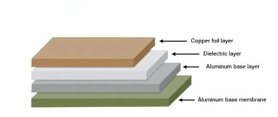
The aluminum substrate acts as a massive heat sink, pulling heat away from solder joints faster than traditional laminates. This rapid dissipation often results in insufficient time above liquidus, causing cold solder joints or poor wetting during reflow. Coefficient of thermal expansion mismatches between the copper traces, dielectric layer, and aluminum base exacerbate warpage under thermal cycling. Surface oxidation on pads further hinders flux activation and solder flow if not addressed. Understanding these mechanisms is crucial for developing effective aluminum PCB reflow profiles.
Excessive peak temperatures can degrade the dielectric, leading to delamination where layers separate. Uneven heating across the board promotes tombstoning, where components lift due to asymmetric solder melting. Voids form from trapped flux gases or moisture if preheating is inadequate. These principles guide the selection of appropriate aluminum PCB solder paste and process parameters.
Common Aluminum PCB Soldering Defects and Their Root Causes
Aluminum PCB soldering defects frequently include cold joints, characterized by dull, grainy appearances from underheating. Solder bridges occur when excess paste connects adjacent pads, often due to improper stencil design or reflow ramp rates. Poor wetting manifests as de-wetted pads where solder beads up instead of spreading evenly, stemming from oxide layers or incompatible flux. Warpage arises from asymmetric copper distribution and thermal stresses during cooling, distorting the board and misaligning components.
Voids and blowholes appear as gas pockets in joints, caused by moisture in the board or paste volatilizing during reflow. Tombstoning affects small passives, lifted by uneven reflow on the heat-sinking aluminum base. Delamination signals excessive heat exposure beyond the dielectric's tolerance, separating layers and creating opens. Identifying these defects early via visual inspection or X-ray allows targeted fixes.
IPC J-STD-001 outlines requirements for soldered electrical assemblies, emphasizing criteria to classify these defects.
Optimizing Aluminum PCB Solder Paste Selection
Choosing the right aluminum PCB solder paste is foundational for reliable joints. Lead-free SAC305 alloys with melting points around 217 degrees C to 221 degrees C offer good compatibility with aluminum substrates. Finer particle sizes, such as Type 4 or Type 5, improve printability on fine-pitch pads and reduce voiding. No-clean or water-soluble fluxes enhance wetting by effectively removing oxides without aggressive residues.
Test paste slump and tackiness to match your stencil thickness and prevent bridging. Store paste at recommended refrigeration temperatures to maintain viscosity. Incompatible pastes lead to poor coalescence on the heat-dissipating surface, so validate with thermal profiling. Proper selection minimizes aluminum PCB soldering defects from the outset.
Developing Effective Aluminum PCB Reflow Profiles
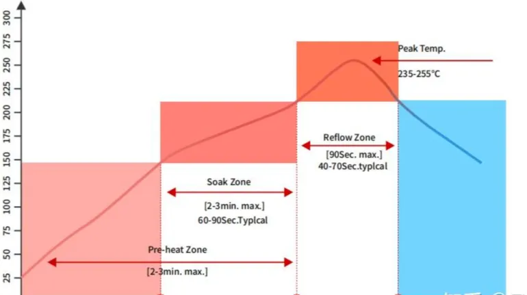
A tailored aluminum PCB reflow profile compensates for the substrate's thermal mass. Start with a preheat stage at 150 degrees C to 180 degrees C for 60 to 90 seconds to drive off volatiles and equalize temperatures. Follow with a soak at 180 degrees C to 200 degrees C for 30 to 60 seconds to activate flux fully. Peak reflow at 235 degrees C to 250 degrees C for 20 to 40 seconds ensures complete melting without overheating the dielectric.
Cool at 2 degrees C to 4 degrees C per second to minimize thermal shock and warpage. Use thermocouples on actual boards to verify profiles, adjusting ramp rates for thicker aluminum cores. Nitrogen atmospheres reduce oxidation during peak dwell. These parameters align with general guidelines while addressing aluminum-specific heat sinking.
JEDEC J-STD-020 provides moisture and reflow sensitivity classifications that inform profile adjustments.
Best Practices for Hand Soldering Aluminum PCBs
Hand soldering suits prototypes but requires precautions for aluminum boards. Preheat the board to 100 degrees C to 150 degrees C on a hot plate to counter heat sinking. Set the iron to 300 degrees C to 350 degrees C with a fine tip for lead-free solder. Apply flux generously before tinning to break oxides and promote flow.
Work quickly to avoid prolonged heat exposure, inspecting each joint for shine and fillet formation. Use fixtures to secure warped boards during assembly. Clean residues promptly to prevent corrosion. These steps yield reliable aluminum PCB assembly in low-volume settings.
Related Reading: Soldering Techniques for Aluminum PCBs: A Practical Guide
Practical Troubleshooting Strategies for Soldering Defects
For cold joints, extend soak time or increase preheat to ensure uniform heating across the aluminum base. Address solder bridges by refining stencil apertures and reducing paste volume, followed by post-reflow AOI inspection. Poor wetting responds to aggressive flux or surface finishes like ENIG, plus thorough pre-cleaning with isopropyl alcohol.
Combat warpage with symmetric layouts, board supports in the oven, and balanced cooling. Voids diminish with moisture-controlled storage per JEDEC guidelines and extended preheats. Delamination calls for dielectric verification and profile peaks below Tg limits. Systematic root cause analysis, including thermal imaging, accelerates fixes.
IPC-A-610 defines acceptability criteria for solder joints, aiding consistent evaluation.
Related Reading: Troubleshooting Cold Solder Joints: A Practical Guide for Electronics Repair
Case Study: Resolving Reflow Issues in LED Driver Assembly
In a typical high-power LED module on aluminum PCB, initial runs showed 15 percent tombstoning and voids. Analysis revealed short soak due to aggressive ramps ignoring the core's heat sink effect. Engineers extended preheat to 90 seconds and soak to 60 seconds, shifting peak to 245 degrees C. Component placement symmetry and fixture supports eliminated warpage.
Post-adjustment yield exceeded 98 percent, with X-ray confirming void-free joints. This underscores profiling on production boards. Similar adjustments apply broadly in aluminum PCB assembly.
Conclusion
Mastering aluminum PCB soldering demands attention to thermal dynamics, precise profiles, and defect-specific fixes. Key takeaways include selecting SAC305 paste, validating reflow with thermocouples, and preheating to counter heat sinking. Implementing these practices reduces aluminum PCB soldering defects, boosts reliability, and streamlines assembly. Electric engineers can leverage standards like IPC J-STD-001 for process control. Prioritize cleanliness, symmetric designs, and inspections for long-term success.
FAQs
Q1: What is the ideal aluminum PCB soldering temperature for reflow processes?
A1: Aluminum PCB reflow profiles typically feature a peak of 235 degrees C to 250 degrees C for lead-free pastes, with preheat at 150 degrees C to 180 degrees C. Extended soak compensates for the aluminum core's heat dissipation. Monitor with thermocouples to avoid exceeding dielectric limits. This ensures proper wetting without defects.
Q2: How do I select aluminum PCB solder paste to minimize defects?
A2: Opt for SAC305 lead-free paste with Type 4 or 5 particles and compatible flux for oxide removal. No-clean types suit most assemblies, reducing post-clean needs. Test for slump and tack to match your process. Proper choice prevents poor wetting and voids in aluminum PCB assembly.
Q3: What causes warpage in aluminum PCB soldering and how to prevent it?
A3: Warpage stems from CTE mismatches and uneven cooling during reflow. Prevent with symmetric copper layouts, oven fixtures, and controlled cooling rates of 2 degrees C to 4 degrees C per second. Uniform preheating distributes stress evenly. This maintains flatness for reliable soldering.
Q4: How can I troubleshoot common aluminum PCB soldering defects like cold joints?
A4: Cold joints result from rapid heat loss; extend preheat and soak times in your reflow profile. Verify flux activity and cleanliness. Re-profile using board-mounted sensors for accuracy. These steps restore joint integrity per industry verification methods.
References
IPC J-STD-001G — Requirements for Soldered Electrical and Electronic Assemblies. IPC, 2017
IPC/JEDEC J-STD-020E — Moisture/Reflow Sensitivity Classification for Nonhermetic Surface Mount Devices. JEDEC, 2014
IPC-A-610H — Acceptability of Electronic Assemblies. IPC, 2019


