 ALLPCB


Introduction
Metal core printed circuit boards, or MCPCBs, play a critical role in applications requiring efficient heat dissipation, such as power electronics, LED lighting, and automotive systems. The choice between copper core PCB and aluminum core PCB directly impacts thermal performance, reliability, and overall cost. Engineers must evaluate MCPCB material comparison factors like thermal conductivity, mechanical properties, and manufacturability to optimize designs. This article provides a factory-driven analysis of copper versus aluminum cores, focusing on key engineering principles and practical selection criteria. By understanding these differences, designers can align material choices with specific thermal and structural demands.
Understanding MCPCBs and Their Core Materials
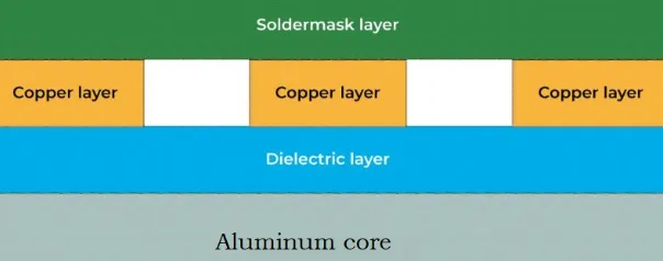
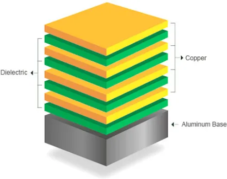
MCPCBs consist of a metal base layer, a thin dielectric insulating layer, and a copper circuit layer, designed to channel heat away from heat-generating components more effectively than standard FR4 boards. Aluminum core PCBs dominate due to their balance of properties, while copper core PCBs serve high-performance needs. The metal core enhances thermal transfer by spreading heat laterally and vertically to heatsinks or the environment. Factory processes for both materials involve lamination under controlled pressure and temperature to ensure bond integrity. Selecting the right core material begins with assessing power density and operating temperatures in the application.
Key Material Properties in MCPCB Material Comparison
Copper and aluminum differ significantly in physical properties that influence MCPCB performance. Copper offers superior thermal conductivity of approximately 400 W/m·K, nearly double that of aluminum alloys ranging from 138 to 238 W/m·K, enabling faster heat spreading in demanding scenarios Aluminum provides a lighter weight with a density about one-third of copper's, reducing overall board mass in weight-sensitive designs. Coefficient of thermal expansion (CTE) values also vary, with copper typically exhibiting lower CTE mismatch risks against copper traces compared to aluminum. Cost considerations favor aluminum, as copper's higher material price elevates production expenses. These properties guide MCPCB material comparison during the prototyping phase.
- Thermal Conductivity: Copper ~400 W/m·K; Aluminum 138–238 W/m·K.
- Density: Copper higher (~8.96 g/cm3); Aluminum lower (~2.7 g/cm3).
- Cost: Copper higher; Aluminum lower.
- Machinability: Copper more challenging; Aluminum easier.
- Typical Applications: Copper for high-power density; Aluminum for general thermal management.
Thermal Conductivity of MCPCB: Core Driver for Performance
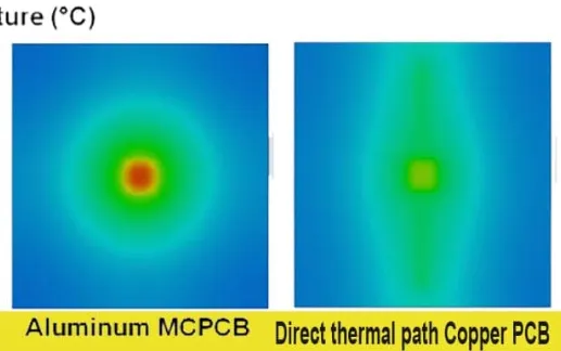
The thermal conductivity of MCPCB determines how effectively heat moves from components through the core to external dissipation points. Copper core PCBs excel here, with their high conductivity minimizing thermal resistance and junction temperatures in high-power devices. Aluminum core PCBs suffice for moderate heat loads, offering adequate performance at lower cost and weight. Dielectric layer thickness critically affects overall conductivity, typically 75–150 microns for balancing insulation and heat transfer. Factory testing verifies these properties using infrared thermography to map hotspots. Engineers should simulate thermal profiles early to
In practice, copper's advantage shines in applications exceeding 50W per square centimeter, where aluminum may require thicker cores or additional vias. IPC-2221 provides guidelines for thermal management in PCB design, emphasizing material selection based on power dissipation needs.
Mechanical and Electrical Considerations
Beyond thermal traits, mechanical strength influences MCPCB reliability under thermal cycling. Copper cores provide higher rigidity and tensile strength, resisting warpage better in multilayer stacks. Aluminum's ductility aids machining but increases warpage risk due to higher CTE, necessitating precise annealing processes. Electrical isolation relies on the dielectric, with both materials supporting high-voltage standoffs when properly specified. Vias and pads must align with core thickness to avoid cracking during drilling. Factory insights highlight copper's edge in vibration-prone environments like automotive modules.
MCPCB Design Considerations for Optimal Selection
MCPCB design considerations include pad layouts, via placement, and heatsink interfaces tailored to core material. For copper core PCBs, wider traces leverage high conductivity, but designers must account for heavier weight in enclosures. Aluminum core PCBs benefit from simpler routing due to easier fabrication, ideal for cost-sensitive prototypes. Thermal vias under hotspots enhance conduction, spaced per IPC-6012 performance specs for rigid boards. Solder mask and silkscreen choices affect surface emissivity for radiative cooling. Simulate CTE mismatches to prevent delamination, especially in reflow soldering.
- Trace Width: Copper—narrower possible; Aluminum—standard widths.
- Via Density: Copper—higher for heat paths; Aluminum—moderate.
- Heatsink Attachment: Copper—thermal epoxy preferred; Aluminum—mechanical clips viable.
- Layer Count: Copper—up to 4 layers feasible; Aluminum—typically single/double.
Board thickness standardization, often 1.5–3.0 mm, balances rigidity and thermal paths. J-STD-020 outlines reflow sensitivity for MCPCBs, guiding dielectric choices.
Pros and Cons: Practical Factory Perspective
Copper core PCBs offer unmatched heat dissipation and durability but at premium cost and added weight, suiting aerospace or RF amplifiers. Aluminum core PCBs deliver solid performance economically, with lightweight appeal for consumer electronics, though limited in extreme thermal loads. Machining aluminum reduces tooling wear, speeding production runs. Both withstand standard IPC Class 2 assembly, but copper demands tighter tolerances. Procurement teams weigh volume against performance; low-volume favors aluminum prototyping.
Best Practices for Implementation
Start with thermal modeling using finite element analysis to compare copper and aluminum options against specs. Specify dielectric thermal conductivity above 1 W/m·K for efficiency. Incorporate filled vias and copper pours for lateral spreading. Validate prototypes via thermal cycling per IPC-A-600 acceptability criteria. Partner with fabs experienced in core lamination to minimize voids. Document design rules for repeatability.
Conclusion
Choosing between copper core PCB and aluminum core PCB hinges on balancing thermal conductivity of MCPCB against cost, weight, and design constraints. Copper excels in high-stakes thermal environments, while aluminum provides versatile, economical solutions. Thorough MCPCB material comparison and adherence to standards ensure reliable outcomes. Engineers gain factory-aligned insights by prioritizing simulation and testing. Optimal selection enhances product longevity and performance across applications.
FAQs
Q1: What is the main difference in thermal conductivity between copper core PCB and aluminum core PCB?
A1: Copper core PCBs typically achieve around 400 W/m·K, roughly double aluminum core PCBs at 138–238 W/m·K, enabling superior heat spreading for high-power components. This gap influences hotspot mitigation in dense designs. Factory lamination optimizes dielectric integration for both. Select based on power density thresholds.
Q2: When should electric engineers prefer copper core PCB over aluminum core PCB?
A2: Opt for copper core PCB in applications exceeding moderate heat loads, like power converters, where its higher thermal conductivity prevents overtemperature failures. Aluminum suits lighter, cost-driven uses. Consider weight and budget alongside simulations. MCPCB design considerations include CTE matching for reliability.
Q3: What are key MCPCB design considerations for thermal management?
A3: Focus on dielectric thickness, thermal vias, and core thickness to maximize conductivity paths. Align with IPC-2221 for trace sizing and power handling. Test warpage post-lamination. Balance single-layer simplicity with multilayer needs. Aluminum eases fabrication, copper boosts performance.
Q4: How does MCPCB material comparison affect manufacturing costs?
A4: Aluminum core PCB lowers costs through cheaper base material and simpler machining versus copper core PCB premiums. Volume production amplifies savings. Factor tooling and yield in quotes. Both follow standard IPC processes.
References
IPC-2221B — Generic Standard on Printed Board Design. IPC, 2012
IPC-6012E — Qualification and Performance Specification for Rigid Printed Boards. IPC, 2015
J-STD-020E — Moisture/Reflow Sensitivity Classification for Nonhermetic Surface Mount Devices. JEDEC, 2014


