 ALLPCB


Are you looking to understand the process of assembling a smart meter PCB? Whether you're a beginner in electronics or an engineer exploring this field, this guide will walk you through every step of smart meter PCB assembly. From surface mount technology (SMT) to through-hole assembly and soldering techniques, we’ve got you covered with practical tips and detailed explanations. Let’s dive into the world of smart meter PCB SMT assembly, smart meter PCB through-hole assembly, and more to help you build reliable and efficient smart meter circuit boards.
What is Smart Meter PCB Assembly?
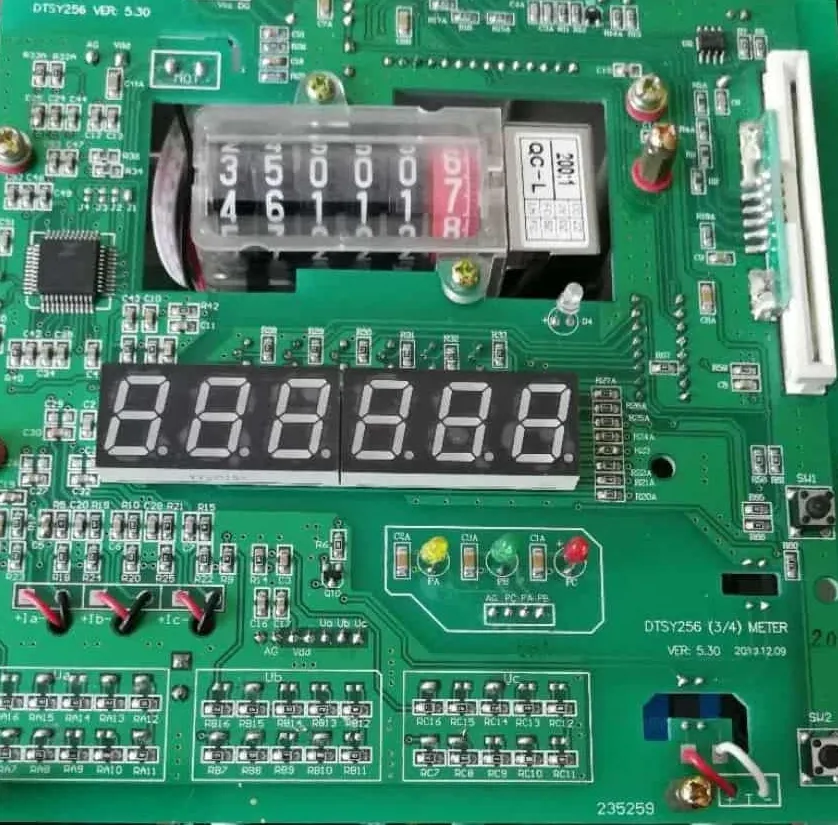
Smart meter PCB assembly refers to the process of building printed circuit boards (PCBs) used in smart meters—devices that measure and monitor energy consumption with advanced digital features. These PCBs are the backbone of smart meters, integrating components like microcontrollers, sensors, and communication modules. Assembling a smart meter PCB involves techniques such as smart meter PCB SMT assembly for tiny components and smart meter PCB through-hole assembly for larger, more robust parts. This guide will break down each stage, ensuring you can follow along even if you're new to PCB assembly.
Why is Smart Meter PCB Assembly Important?
Smart meters are critical in modern energy management, providing real-time data to both consumers and utility providers. A well-assembled PCB ensures the smart meter functions accurately, withstands environmental challenges, and maintains a long lifespan. Errors in assembly, such as poor soldering or incorrect component placement, can lead to malfunctions or inaccurate readings. By mastering the smart meter PCB soldering process and other assembly steps, you can create reliable devices that meet industry standards.
 ."
."
Overview of the Smart Meter PCB Assembly Process
The assembly process for a smart meter PCB can be broadly divided into several key stages: design preparation, component placement, soldering, and testing. Each stage requires precision to ensure the final product works as intended. Below, we’ll explore these steps in detail, focusing on techniques like smart meter PCB reflow soldering and the use of a smart meter PCB component placement machine.
Step 1: Preparing the PCB Design and Materials
Before assembly begins, you need a finalized PCB design. This design includes the layout of traces, pads, and vias that connect components. For smart meter PCBs, the design must account for high-frequency signals (often around 2.4 GHz for wireless communication modules) and power efficiency to minimize energy loss. Once the design is ready, gather all necessary materials, including the bare PCB, electronic components (resistors, capacitors, ICs), solder paste, and assembly tools.
Ensure the PCB is clean and free from dust or debris, as contaminants can interfere with soldering. Also, verify that all components match the bill of materials (BOM) to avoid delays during assembly. This preparation is the foundation of a smooth smart meter PCB SMT assembly or through-hole process.
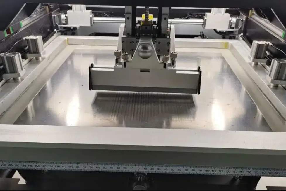
Step 2: Solder Paste Application for SMT Assembly
In smart meter PCB SMT assembly, the first active step is applying solder paste to the PCB. Solder paste is a mixture of tiny solder particles and flux, which helps components stick to the board before soldering. Use a stencil—a thin metal sheet with cutouts matching the PCB’s pads—to apply the paste precisely. Place the stencil over the PCB and use a squeegee to spread the paste evenly across the openings.
Accuracy is crucial here. Misaligned or excessive paste can cause short circuits or weak connections. For smart meter PCBs, where components like surface-mount resistors (often as small as 0402 size, measuring 0.4mm x 0.2mm) are common, precision in solder paste application ensures reliable connections.
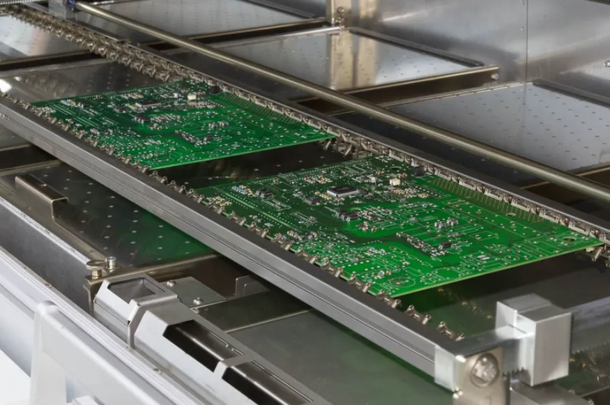
Step 3: Component Placement with a Machine
Once the solder paste is applied, it’s time to place the components on the PCB. For smart meter PCB SMT assembly, this is typically done using a smart meter PCB component placement machine, also known as a pick-and-place machine. These automated systems can place thousands of components per hour with incredible accuracy, which is essential for the high-density layouts of smart meter PCBs.
The machine uses a vacuum nozzle to pick up components from reels or trays and places them onto the solder paste-covered pads. For instance, a typical smart meter PCB might include a microcontroller with a placement tolerance of ±0.1mm to ensure proper alignment with fine-pitch pins. If you’re working manually (for small-scale or prototype projects), use tweezers and a steady hand, but be prepared for a slower and more error-prone process.
Step 4: Reflow Soldering for SMT Components
After component placement, the PCB undergoes smart meter PCB reflow soldering. This process involves heating the board in a reflow oven to melt the solder paste, creating permanent electrical connections between components and pads. The oven follows a specific temperature profile, typically reaching a peak of about 245°C for lead-free solder, to ensure proper melting without damaging components.
The reflow process has several zones: preheat (to activate flux), soak (to stabilize temperature), reflow (to melt solder), and cooling (to solidify connections). For smart meter PCBs, where thermal management is critical due to power components, monitoring the temperature profile prevents issues like thermal shock to sensitive ICs.
Step 5: Through-Hole Component Assembly
While SMT dominates modern PCB assembly, smart meter PCB through-hole assembly is still used for components like connectors, transformers, or high-power resistors that require extra mechanical strength. In this method, component leads are inserted into pre-drilled holes on the PCB, and the leads are soldered on the opposite side.
Through-hole assembly can be manual or automated. Manually, you insert components by hand and solder them using a soldering iron. Automated systems use wave soldering, where the PCB passes over a wave of molten solder (typically at 260°C) to connect all through-hole leads at once. For smart meter PCBs, through-hole components like power connectors must handle currents up to 10A or more, so secure soldering is vital.
Step 6: Soldering Process for Through-Hole Components
The smart meter PCB soldering process for through-hole components requires attention to detail to avoid cold solder joints or overheating. If soldering manually, use a soldering iron with a temperature of around 300°C for lead-free solder. Apply the iron to the pad and lead simultaneously, then feed solder wire into the joint until it flows evenly. The process should take no more than 2-3 seconds per joint to prevent damage to the PCB or component.
For wave soldering, ensure the PCB is properly aligned on the conveyor to avoid uneven solder distribution. After soldering, inspect the joints for shininess and a smooth, conical shape—indicators of a good connection. Poor soldering can lead to intermittent failures in smart meters, especially under varying temperatures or vibrations.
Step 7: Inspection and Quality Control
Once soldering is complete, inspect the PCB to ensure all connections are secure and components are correctly placed. Use tools like automated optical inspection (AOI) systems to detect issues such as misaligned components or insufficient solder. For smart meter PCBs, where reliability is non-negotiable, AOI can scan for defects at a resolution of 5 micrometers, catching even tiny flaws.
Additionally, perform electrical testing to verify functionality. For example, test the impedance of critical traces (often around 50 ohms for RF lines in smart meters) to ensure signal integrity. If any issues are found, rework the PCB by desoldering and replacing faulty components or fixing solder joints.
Step 8: Cleaning and Final Assembly
After inspection, clean the PCB to remove flux residue or contaminants that could cause corrosion over time. Use isopropyl alcohol and a brush or an ultrasonic cleaner for thorough results. Once clean, the PCB is ready for final assembly into the smart meter housing. Ensure proper alignment of the PCB with mounting points and connectors to avoid stress on solder joints.
For smart meter PCBs, environmental protection is key. Apply conformal coating if the meter will be exposed to moisture or dust, as this adds a protective layer without affecting electrical performance. Finally, conduct a functional test of the assembled smart meter to confirm accurate energy measurement and data transmission.
Tools and Equipment for Smart Meter PCB Assembly
To successfully assemble a smart meter PCB, you’ll need the right tools. Here’s a list of essentials for both smart meter PCB SMT assembly and smart meter PCB through-hole assembly:
- Solder Paste Stencil: For precise application in SMT assembly.
- Pick-and-Place Machine: For automated component placement in smart meter PCB component placement machine setups.
- Reflow Oven: Essential for smart meter PCB reflow soldering.
- Soldering Iron: For manual smart meter PCB soldering process in through-hole assembly.
- Inspection Tools: Magnifying glass or AOI systems for quality checks.
- Cleaning Supplies: Alcohol and brushes for post-soldering cleanup.
Common Challenges in Smart Meter PCB Assembly
Assembling smart meter PCBs comes with challenges, especially for beginners. One common issue in smart meter PCB SMT assembly is tombstoning, where small components stand upright due to uneven heating during reflow. To prevent this, ensure uniform solder paste application and monitor reflow temperature profiles closely.
In smart meter PCB through-hole assembly, overheating components with a soldering iron can cause damage. Limit soldering time and use a heat sink if needed. Additionally, smart meter PCBs often handle high-frequency signals, so improper trace layout or soldering can introduce noise, affecting readings. Always follow design guidelines for impedance matching and grounding.
Tips for Beginners in Smart Meter PCB Assembly
If you’re new to PCB assembly, here are some practical tips to ensure success:
- Start with a simple design to practice your skills before tackling complex smart meter PCBs.
- Use proper lighting and magnification to see small components clearly during smart meter PCB SMT assembly.
- Keep your workspace organized to avoid mixing up components or losing small parts.
- Double-check polarity for components like diodes and capacitors to prevent reverse installation.
- Practice patience, especially during the smart meter PCB soldering process, as rushing can lead to mistakes.
Conclusion
Assembling a smart meter PCB may seem daunting at first, but by following this step-by-step guide, you can master the process with practice. From smart meter PCB SMT assembly to smart meter PCB through-hole assembly, each stage—whether it’s using a smart meter PCB component placement machine or performing smart meter PCB reflow soldering—plays a vital role in creating a functional and reliable device. With the right tools, techniques, and attention to detail, you’ll be well on your way to building high-quality smart meter PCBs that power the future of energy monitoring.
By focusing on precision and quality at every step of the smart meter PCB soldering process, you ensure the final product meets the demands of modern energy systems. Keep learning, stay patient, and soon you’ll be confident in handling even the most complex PCB assemblies.


