 ALLPCB


Are you struggling to choose the right PCB material for impedance control in your high-speed designs? The key lies in selecting a laminate with the correct dielectric constant and material properties to ensure signal integrity and performance. In this comprehensive guide, we’ll walk you through everything you need to know about PCB material properties for impedance, how to choose the right laminate, and the role of dielectric constant in PCB materials. Whether you’re designing for high-frequency applications or complex multilayer boards, this guide will help you make informed decisions for optimal results.
Why PCB Material Selection Matters for Impedance Control
When designing printed circuit boards (PCBs) for high-speed or high-frequency applications, impedance control is critical. Impedance mismatches can lead to signal reflections, data loss, and degraded performance. The material you choose for your PCB plays a huge role in determining how well you can control impedance. Different materials have unique electrical properties, such as dielectric constant (Dk) and dissipation factor (Df), which directly impact signal transmission and integrity.
In this guide, we’ll break down the essentials of PCB material selection with a focus on impedance control. By understanding the relationship between material properties and impedance, you can ensure your designs meet performance requirements and avoid costly redesigns.
Understanding Impedance Control in PCB Design
Impedance control refers to the management of the electrical impedance of traces on a PCB to ensure consistent signal transmission. In high-speed designs, such as those for USB, HDMI, or RF applications, maintaining a specific impedance (often 50 ohms or 100 ohms) is essential to prevent signal distortion. Impedance is influenced by several factors, including trace width, trace thickness, spacing, and the dielectric properties of the PCB material.
The dielectric material, or laminate, acts as an insulator between conductive layers and significantly affects impedance. A material with a stable dielectric constant ensures that signals travel at a predictable speed, minimizing delays and reflections. If the material’s properties vary with frequency or temperature, impedance can fluctuate, leading to performance issues.
Key PCB Material Properties for Impedance Control
When selecting a PCB material for impedance control, you need to focus on specific properties that influence electrical performance. Let’s explore the most important factors to consider, especially when targeting keywords like "PCB material properties impedance."
1. Dielectric Constant (Dk)
The dielectric constant, often abbreviated as Dk, measures a material’s ability to store electrical energy in an electric field. It directly affects the speed of signal propagation through the PCB. A lower Dk value means signals travel faster, which is crucial for high-speed designs. Common Dk values for PCB materials range from 2.2 to 4.5, depending on the laminate.
For impedance control, consistency in Dk is vital. Variations in the dielectric constant across the board or with frequency can cause impedance mismatches. For example, a material with a Dk of 4.0 might be suitable for a 50-ohm impedance design, but if the Dk shifts to 4.2 at higher frequencies, signal integrity could suffer.
2. Dissipation Factor (Df)
The dissipation factor, or Df, indicates how much signal energy is lost as heat in the material. A lower Df is preferred for high-frequency applications because it reduces signal loss. Materials with a Df below 0.005 are often ideal for designs requiring strict impedance control, as they minimize energy loss and maintain signal strength over long traces.
3. Thermal Stability
Temperature changes can affect a material’s dielectric constant and dissipation factor, leading to impedance variations. Materials with high thermal stability ensure consistent performance even in harsh environments. Look for laminates with a low coefficient of thermal expansion (CTE) to avoid physical stress on traces and vias, which can also impact impedance.
Choosing PCB Laminate for Impedance Control
Selecting the right laminate is a critical step in achieving impedance control. With the keyword "choosing PCB laminate impedance" in mind, let’s explore how to make the best choice for your project. The laminate you select should align with your design’s frequency, speed, and environmental requirements.
1. FR-4: The Standard Choice
FR-4 is the most widely used PCB material due to its affordability and versatility. It has a dielectric constant of around 4.3 to 4.5 at 1 MHz, making it suitable for many low- to mid-frequency applications. However, FR-4’s Dk can vary with frequency and temperature, which may pose challenges for high-speed designs requiring tight impedance control.
For designs operating below 1 GHz, FR-4 can often meet impedance requirements with proper trace design. However, for frequencies above 1 GHz, you might notice signal loss and impedance inconsistencies due to its higher Df (around 0.02).
2. High-Performance Laminates for High-Speed Designs
For applications demanding precise impedance control, high-performance laminates are a better choice. These materials offer lower and more stable Dk values, as well as reduced signal loss. Some popular options include:
- Low-Dk Materials: With Dk values between 2.2 and 3.0, these laminates are ideal for ultra-high-speed designs, such as 5G or automotive radar systems.
- RF-Specific Materials: Designed for radio frequency applications, these materials maintain consistent impedance at frequencies up to 10 GHz or higher.
While these laminates cost more than FR-4, they provide the stability needed for critical impedance control in advanced designs.
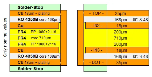
3. Hybrid Stackups for Cost-Performance Balance
In multilayer PCBs, you can use a hybrid approach by combining standard materials like FR-4 with high-performance laminates in critical layers. For example, use a low-Dk material for high-speed signal layers and FR-4 for power and ground planes. This strategy helps manage costs while achieving the necessary impedance control.
Dielectric Constant in PCB Materials: A Deep Dive
Since "dielectric constant PCB materials" is a key focus, let’s dive deeper into how Dk impacts impedance control and material selection. The dielectric constant affects the capacitance between traces and ground planes, which in turn influences the characteristic impedance of a trace.
The relationship between impedance (Z) and dielectric constant can be approximated using the formula for a microstrip transmission line:
Z = (87 / √(Dk + 1.41)) * ln(5.98 * H / (0.8 * W + T))
Where:
- Z is the impedance in ohms
- Dk is the dielectric constant
- H is the height of the dielectric layer
- W is the trace width
- T is the trace thickness
From this formula, you can see that a higher Dk results in lower impedance for the same trace dimensions. Therefore, if you’re targeting a specific impedance, such as 50 ohms, you’ll need to adjust trace width or choose a material with an appropriate Dk.
For high-speed designs, materials with a lower Dk (closer to 2.2) allow for wider traces while maintaining the desired impedance. Wider traces are easier to manufacture and less prone to signal loss, making low-Dk materials advantageous for demanding applications.
Factors to Consider Beyond Material Properties
While material properties like Dk and Df are central to impedance control, other factors also play a role in material selection. Keep these in mind to ensure a successful design:
1. Frequency Range
The operating frequency of your design determines the material’s suitability. At frequencies above 1 GHz, standard materials may exhibit significant signal loss and impedance variation. High-frequency laminates with stable Dk and low Df are necessary for applications like 5G, microwave, or satellite communications.
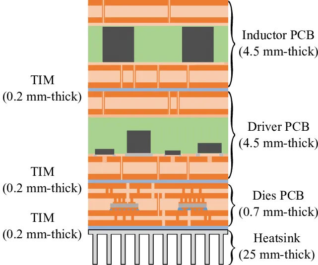
2. Board Thickness and Layer Count
Thicker boards and multilayer designs can complicate impedance control due to increased parasitic capacitance. Choose a material that supports the required dielectric thickness while maintaining a consistent Dk across layers.
3. Environmental Conditions
If your PCB will operate in extreme temperatures or high humidity, select a material with excellent thermal and moisture resistance. Some laminates are specifically engineered to withstand harsh conditions without degrading in performance.
Practical Tips for PCB Material Selection
To wrap up this guide, here are actionable tips to help you choose the right material for impedance control:
- Define Impedance Requirements Early: Determine the target impedance (e.g., 50 ohms for single-ended or 100 ohms for differential pairs) before selecting a material.
- Use Simulation Tools: Leverage PCB design software to simulate impedance based on material properties and trace geometry. This helps identify potential issues before fabrication.
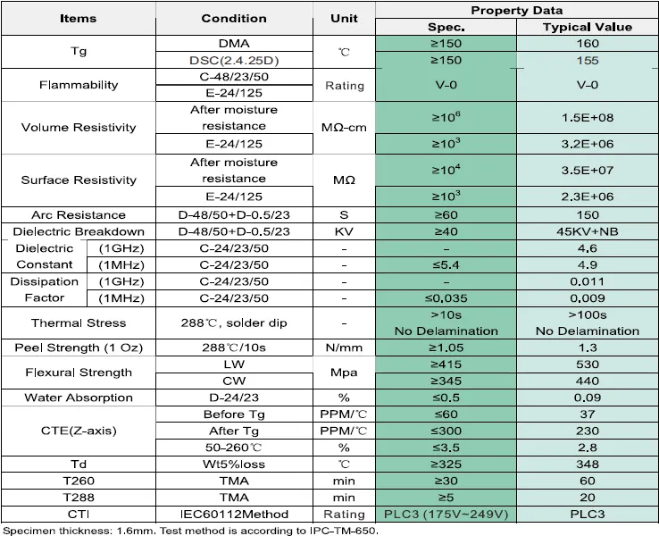
- Consult Material Datasheets: Review the Dk, Df, and thermal properties provided by material manufacturers to ensure compatibility with your design.
- Test Prototypes: Build and test prototypes with your chosen material to validate impedance and signal integrity under real-world conditions.
Conclusion: Making the Right Choice for Impedance Control
Selecting the right PCB material for impedance control is a critical step in ensuring the success of high-speed and high-frequency designs. By focusing on key material properties like dielectric constant and dissipation factor, and by understanding how these factors influence impedance, you can make informed decisions that enhance signal integrity and performance.
Whether you’re working with standard materials for cost-effective designs or high-performance laminates for cutting-edge applications, the principles outlined in this guide will help you navigate the complexities of PCB material selection. Remember to consider your design’s specific requirements, including frequency, environment, and budget, to strike the perfect balance between performance and practicality.
With the right material in hand, you’ll be well on your way to designing PCBs that meet even the most stringent impedance control standards. Trust in a thorough understanding of PCB material properties for impedance, and you’ll achieve reliable, high-quality results every time.


