 ALLPCB


If you're looking to secure a printed circuit board (PCB) to an enclosure or chassis, non-plated through-holes (NPTH) for mechanical mounting are a critical design element. These holes, unlike their plated counterparts, are not coated with conductive material and are specifically used for structural purposes like screw placement and PCB support. In this comprehensive guide, we'll explore the best practices and design tips for using NPTH in mechanical mounting, covering key areas such as PCB mounting holes, screw placement, vibration dampening, stress relief, and enclosure design. Whether you're a seasoned engineer or a beginner, this post will provide actionable insights to ensure your PCB designs are robust and reliable.
What Are Non-Plated Through-Holes (NPTH) and Why Use Them for Mechanical Mounting?
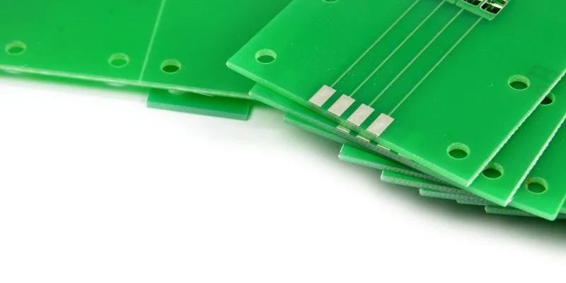
Non-plated through-holes are holes drilled into a PCB that do not have a conductive copper layer on their walls. Unlike plated through-holes, which are often used for electrical connections, NPTH are primarily intended for mechanical purposes. These holes serve as mounting points to attach the PCB to an enclosure or other hardware using screws, standoffs, or other fasteners.
The main advantage of using NPTH for mechanical mounting is their isolation from the electrical circuits on the board. This prevents unintended electrical connections or shorts that could occur if a conductive screw or fastener comes into contact with a plated hole. Additionally, NPTH can be designed with larger diameters to accommodate various fastener sizes, ensuring a secure fit without risking damage to the board's electrical integrity.
In the following sections, we'll dive into the best practices for designing and using NPTH for mechanical mounting, ensuring your PCB remains stable and functional even under stress or vibration.
Designing PCB Mounting Holes with NPTH: Key Considerations
When designing PCB mounting holes using NPTH, precision and forethought are essential to ensure the board's stability and longevity. Here are some critical factors to consider:
- Hole Size and Tolerance: The diameter of the NPTH should match the fastener size (e.g., screw or standoff) with a small tolerance to allow for easy assembly while preventing excessive movement. For example, a common M3 screw has a diameter of 3 mm, so the hole might be designed at 3.2 mm to 3.3 mm to account for manufacturing variances and ease of insertion.
- Location: Place mounting holes in areas of the PCB that are free from critical components and traces to avoid interference. Typically, holes are positioned near the corners of the board for balanced support, but the exact placement depends on the enclosure design and weight distribution.
- Clearance Around Holes: Ensure there is enough clearance around the NPTH to prevent stress fractures or damage during assembly. A general rule of thumb is to maintain a clearance of at least 2 mm from the edge of the hole to any nearby components or traces.
- Board Thickness: The thickness of the PCB affects how securely it can be mounted. Standard PCB thicknesses range from 0.8 mm to 1.6 mm, and thicker boards may provide better support for heavier assemblies. Choose a thickness that matches the mechanical demands of your project.
By carefully designing the size, placement, and surrounding clearance of NPTH, you can create a robust mounting system that withstands mechanical stress and prevents damage during installation.
Screw Placement Techniques for Secure PCB Mounting
Screw placement is a fundamental aspect of using NPTH for mechanical mounting. The right approach ensures the PCB is firmly attached without introducing stress or risking damage. Here are some best practices for screw placement:
- Use Appropriate Fastener Types: Select screws or standoffs that match the NPTH size and the material of the enclosure. For instance, M2 or M3 screws are commonly used for smaller PCBs, while larger boards might require M4 or M5 screws for added strength.
- Avoid Over-Tightening: Over-tightening screws can cause stress fractures in the PCB material, especially near the mounting holes. Use a torque screwdriver to apply a controlled force, typically between 0.5 Nm and 1.0 Nm for M3 screws, depending on the board material (e.g., FR4).
- Incorporate Washers or Spacers: Adding washers or spacers between the screw head and the PCB can distribute the load more evenly, reducing the risk of cracking. Nylon or plastic washers are often preferred to avoid electrical conductivity issues.
- Balance the Load: Distribute screws evenly across the PCB to prevent uneven stress. For a rectangular board, placing screws at all four corners provides balanced support, while larger or heavier boards may require additional mounting points in the center or along the edges.
Proper screw placement not only secures the PCB but also minimizes the risk of mechanical failure over time, especially in environments with frequent handling or vibration.
PCB Support Methods to Enhance Stability
Beyond screws and mounting holes, additional PCB support methods can significantly improve the board's stability, especially for larger or heavier designs. Here are some effective strategies:
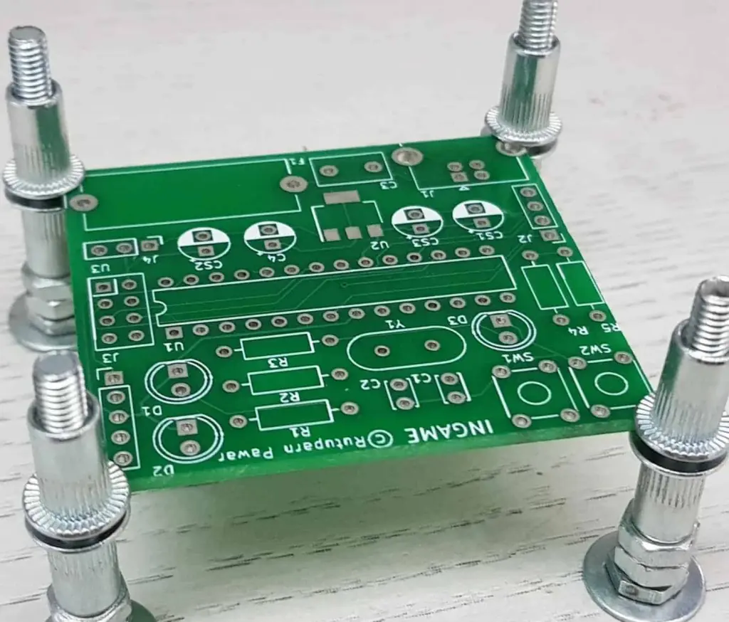
- Standoffs: Standoffs are cylindrical spacers that elevate the PCB above the mounting surface, providing clearance for components on the underside and preventing short circuits. They are often used with NPTH and come in various heights (e.g., 5 mm to 20 mm) to suit different designs.
- Support Pillars: For larger PCBs, adding support pillars or posts in the middle of the board can prevent sagging or flexing under weight. These pillars can be attached to the enclosure base and aligned with NPTH on the PCB.
- Edge Supports: Some enclosures include slots or rails that support the edges of the PCB, reducing the load on individual mounting holes. This method is particularly useful for DIN rail-mounted systems or industrial applications.
Implementing these support methods alongside NPTH ensures that the PCB remains stable, even in demanding conditions, and reduces the risk of mechanical stress on critical components.
Vibration Dampening Strategies for PCB Protection
In environments where vibration is a concern, such as automotive or industrial applications, protecting the PCB from excessive movement is crucial. Vibration can loosen fasteners, cause fatigue in solder joints, or even lead to component failure. Here are some vibration dampening strategies for designs using NPTH:
- Use Rubber Grommets: Placing rubber or silicone grommets between the PCB and the fastener can absorb vibrations and reduce the transmission of mechanical shock. Grommets with a diameter slightly larger than the NPTH (e.g., 0.5 mm larger) work best.
- Apply Damping Pads: Adhesive damping pads or foam can be placed between the PCB and the enclosure to further absorb vibrations. These pads are often made of materials like neoprene or silicone and come in thicknesses ranging from 1 mm to 3 mm.
- Secure Mounting Points: Ensure all mounting points are tightly secured, and consider using lock washers or thread-locking compounds on screws to prevent loosening over time due to vibration.
- Optimize Hole Placement: Position NPTH mounting holes to distribute vibrational forces evenly across the board. For instance, placing holes closer to high-vibration areas can help stabilize the PCB more effectively.
By incorporating these vibration dampening techniques, you can extend the lifespan of your PCB and protect sensitive components from damage in harsh environments.
Stress Relief in PCB Design with NPTH
Mechanical stress from mounting or environmental factors can cause cracks, delamination, or component failure on a PCB. Using NPTH for mounting provides an opportunity to design for stress relief. Here’s how to minimize stress in your PCB design:
- Avoid Overloading Mounting Points: Don’t rely on a single NPTH to bear the entire weight or stress of the PCB. Distribute the load across multiple mounting holes to reduce localized stress. For a medium-sized PCB (e.g., 100 mm x 150 mm), using at least four mounting points is recommended.
- Use Larger Hole Clearances: Designing NPTH with slightly larger diameters than the fastener allows for minor misalignments during assembly, reducing stress caused by forced fitting.
- Reinforce Hole Areas: For PCBs under high mechanical stress, consider adding reinforcement around NPTH, such as thicker copper rings (even if non-plated) or additional fiberglass layers in multi-layer boards, to strengthen the area.
- Account for Thermal Expansion: In environments with temperature fluctuations, materials expand and contract at different rates. Design NPTH with enough clearance to accommodate thermal expansion of the PCB (typically 10-15 μm per degree Celsius for FR4 material) and prevent cracking.
By focusing on stress relief during the design phase, you can create a PCB that withstands mechanical and thermal challenges without compromising performance.
Enclosure Design Tips for NPTH Mechanical Mounting
The enclosure or chassis that houses the PCB plays a significant role in the effectiveness of NPTH mechanical mounting. A well-designed enclosure complements the PCB's mounting strategy and enhances overall durability. Here are some tips for enclosure design:
- Align Mounting Points: Ensure the enclosure has pre-drilled holes or mounting bosses that align perfectly with the NPTH on the PCB. Misalignment can introduce stress or make assembly difficult. A tolerance of ±0.1 mm is ideal for alignment precision.
- Provide Adequate Space: Design the enclosure with enough internal space to accommodate the PCB, components, and any standoffs or spacers. For example, a clearance of at least 5 mm above tall components like capacitors or connectors prevents contact with the enclosure lid.
- Material Selection: Choose enclosure materials that match the application’s requirements. Plastic enclosures are lightweight and non-conductive, while metal enclosures offer better shielding and durability but may require insulating spacers to prevent shorts with the PCB.
- Incorporate Ventilation: If the PCB generates heat, design the enclosure with ventilation slots or holes to dissipate heat while ensuring mounting points remain secure. Position ventilation away from NPTH to avoid weakening the structure.
A thoughtfully designed enclosure not only protects the PCB but also ensures that the NPTH mounting system functions as intended, providing a secure and stable setup.
Common Mistakes to Avoid with NPTH Mechanical Mounting
Even with the best intentions, certain mistakes can compromise the effectiveness of NPTH for mechanical mounting. Here are some pitfalls to watch out for:
- Using Plated Holes for Mounting: Plated through-holes can create unintended electrical connections with conductive fasteners, leading to shorts. Always use NPTH for mechanical mounting unless grounding is specifically required.
- Ignoring Clearance: Placing NPTH too close to components or board edges can lead to cracks or interference during assembly. Always adhere to clearance guidelines.
- Neglecting Environmental Factors: Failing to account for vibration, thermal expansion, or humidity can result in mechanical failure over time. Design with the operating environment in mind.
- Skipping Prototyping: Without testing the mounting design in a prototype, alignment issues or stress points may go unnoticed until production, leading to costly redesigns.
By avoiding these common errors, you can ensure a more reliable and durable mounting solution for your PCB.
Conclusion: Mastering NPTH for Mechanical Mounting
Non-plated through-holes are a vital tool for mechanical mounting in PCB design, offering a secure and electrically isolated way to attach boards to enclosures or chassis. By following the best practices and design tips outlined in this guide—such as optimizing PCB mounting holes, ensuring proper screw placement, enhancing PCB support, implementing vibration dampening, designing for stress relief, and considering enclosure design—you can create robust and reliable assemblies that stand the test of time.
Whether you're working on a small hobby project or a large industrial application, paying attention to the details of NPTH design will pay off in improved performance and durability. Take the time to plan your mounting strategy carefully, and you'll avoid common pitfalls while achieving a professional-grade result.


