 ALLPCB


In the world of PCB design, ensuring accuracy and functionality before production is critical. One of the most effective ways to achieve this is by using 3D visualization tools. If you're wondering how to leverage Eagle 3D visualization for design verification, you're in the right place. With Eagle's integration with powerful platforms like Fusion 360, you can create detailed 3D models of your PCB layouts, detect potential issues like component collisions, and verify your design with precision—all before sending it to manufacturing.
In this comprehensive guide, we'll dive deep into the benefits of Eagle 3D PCB visualization, explore how Eagle Fusion 360 integration enhances the process, and walk you through practical steps for Eagle collision detection and Eagle design verification. Whether you're a beginner or a seasoned engineer, this post will equip you with actionable insights to optimize your workflow and produce error-free designs.
Why 3D Visualization Matters in PCB Design
PCB design is no longer just about 2D schematics and layouts. As electronic devices become more compact and complex, visualizing a design in three dimensions is essential for catching errors that might not be obvious on a flat screen. Imagine designing a board with tight component spacing—without a 3D view, it's nearly impossible to spot if a tall capacitor interferes with a nearby connector. This is where Eagle 3D visualization shines, offering a realistic perspective to ensure every part fits perfectly.
Using 3D visualization in Eagle helps engineers:
- Identify physical interferences between components.
- Verify enclosure compatibility for the PCB.
- Improve communication with clients or team members by presenting a tangible model.
- Reduce costly revisions by catching errors early in the design phase.
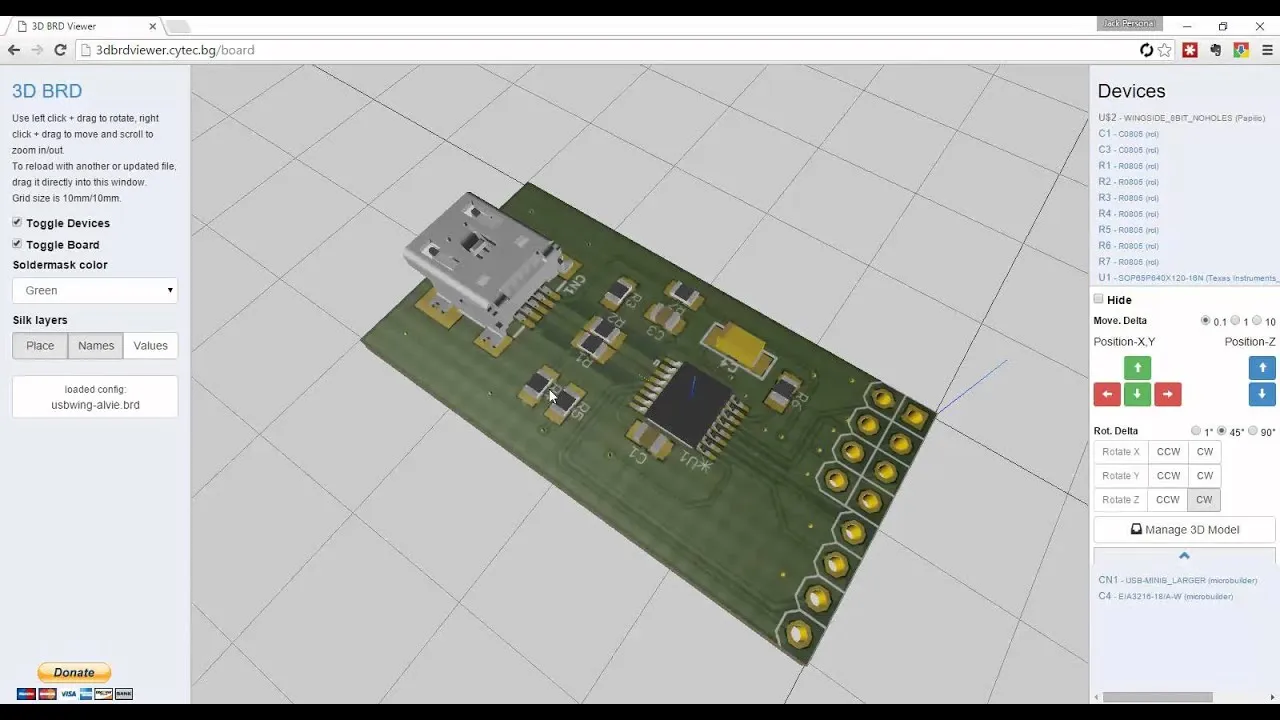
Getting Started with Eagle 3D Visualization
Eagle, a popular PCB design software, offers robust tools for creating and viewing 3D models of your layouts. While earlier versions of Eagle had limited 3D capabilities, its integration with a leading design platform has taken Eagle 3D PCB visualization to the next level. This synergy allows you to export your board designs into a 3D environment where you can manipulate and inspect every detail.
To begin, ensure you have the latest version of Eagle installed. Follow these steps to access 3D visualization:
- Open your PCB layout in Eagle.
- Navigate to the "View" menu and select the 3D view option, or use the dedicated 3D export feature if you're integrating with another design tool.
- Assign 3D models to components if they aren’t already linked. Many libraries in Eagle come with pre-built 3D models, but you may need to import or create custom models for unique parts.
- Export the design to a compatible 3D platform for a more detailed rendering and analysis.
By following these steps, you can transform a flat layout into a dynamic Eagle 3D PCB model, making it easier to spot potential issues.
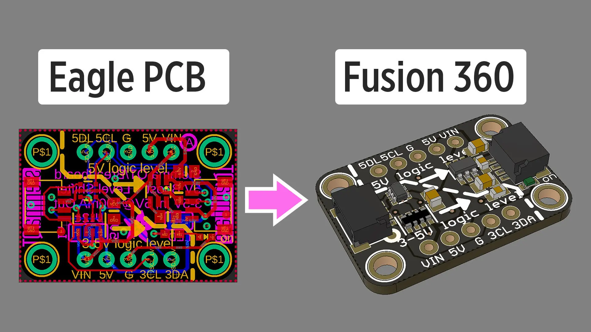
Leveraging Eagle Fusion 360 Integration for Advanced Visualization
One of the standout features of modern Eagle versions is the seamless integration with a comprehensive design platform. This Eagle Fusion 360 integration allows you to push your PCB designs into a 3D environment where you can not only visualize the board but also design the enclosure, test fitment, and simulate real-world conditions.
Here’s how this integration enhances Eagle design verification:
- Unified Workflow: Design both the PCB and its mechanical enclosure in one ecosystem, ensuring perfect alignment. For example, if your board dimensions are 100mm x 50mm, you can model an enclosure with precise internal clearances of 2mm on all sides.
- Real-Time Updates: Changes made in Eagle automatically reflect in the 3D platform, so if you adjust a component’s position, the 3D model updates instantly.
- Thermal and Structural Analysis: Beyond visualization, you can simulate heat dissipation (e.g., identifying hotspots above 85°C) or check if the board withstands mechanical stress.
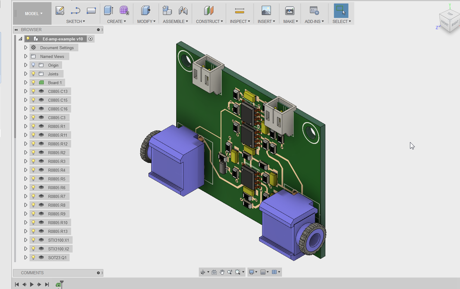
To use this integration, export your Eagle design using the built-in synchronization tool. Once in the 3D environment, you can rotate, zoom, and inspect every angle of your PCB, ensuring no detail is overlooked.
Collision Detection: Preventing Costly Design Errors
One of the most powerful aspects of 3D visualization is Eagle collision detection. When components are placed too close together or overlap in height, it can lead to assembly issues or even short circuits. For instance, if a surface-mount resistor with a height of 1.2mm is placed under a connector with a clearance of only 1mm, a collision occurs, potentially causing a failure.
With Eagle’s 3D tools and integration with advanced platforms, you can:
- Detect physical overlaps between components in the 3D view.
- Check if the PCB fits within the intended enclosure without interference (e.g., ensuring a 0.5mm gap between the board edge and enclosure walls).
- Adjust component placement in real-time to resolve conflicts.
To perform collision detection, load your 3D model and use the inspection tools to highlight areas where components or structures intersect. Some platforms even provide automated alerts for potential collisions, saving you time during Eagle design verification.
Design Verification: Ensuring Functionality with 3D Tools
Design verification is the final step before sending your PCB for fabrication, and 3D visualization plays a crucial role in this process. Eagle design verification using 3D tools goes beyond just checking for collisions—it helps confirm that your design meets all functional and manufacturing requirements.
Key aspects of design verification with Eagle 3D visualization include:
- Component Clearance: Ensure proper spacing for heat dissipation. For example, high-power components like voltage regulators might require a 3mm clearance to avoid overheating.
- Signal Integrity: While not directly visible in 3D, visualizing trace paths in relation to component placement can help identify potential crosstalk issues, especially for high-speed signals operating at 1GHz or above.
- Manufacturability: Check if component heights and placements align with assembly processes. For instance, automated pick-and-place machines may struggle with components taller than 10mm if not positioned correctly.
By thoroughly inspecting your design in a 3D environment, you can minimize errors and ensure a smooth transition from design to production.
Practical Tips for Maximizing Eagle 3D Visualization
To get the most out of Eagle 3D PCB tools, consider these practical tips:
- Update Component Libraries: Always use libraries with accurate 3D models. If a component lacks a 3D model, download or create one with precise dimensions (e.g., a 0805 resistor at 2mm x 1.25mm x 0.5mm).
- Collaborate with Mechanical Teams: Share your 3D models with mechanical engineers to ensure the PCB integrates seamlessly with the product’s housing.
- Use Realistic Textures: When visualizing in a 3D platform, apply realistic materials (e.g., copper for traces, green for solder mask) to make the model more intuitive for stakeholders.
- Simulate Real-World Conditions: If possible, use simulation features to test how your design handles temperature rises (e.g., a 40°C ambient environment) or mechanical stress.
These strategies will help you create more accurate designs and streamline the verification process.
Benefits of 3D Visualization for Collaboration and Client Communication
Beyond technical advantages, Eagle 3D visualization also improves collaboration. When working with clients or non-technical stakeholders, presenting a 3D model is far more effective than a 2D schematic. A realistic view of the PCB, complete with components and enclosures, helps everyone understand the design’s look and feel.
For instance, if you're designing a board for a compact IoT device with dimensions of 30mm x 30mm, a 3D render can demonstrate how it fits within a small casing, reassuring clients about space constraints. This visual aid bridges the gap between technical details and practical expectations, fostering trust and clarity.
Overcoming Common Challenges in Eagle 3D Visualization
While 3D visualization offers immense benefits, it’s not without challenges. Here are some common hurdles and how to address them:
- Missing 3D Models: If a component lacks a 3D model, search for compatible models in online libraries or create a basic placeholder with accurate dimensions (e.g., a 5mm x 5mm x 2mm box for an IC).
- Performance Issues: Large designs with hundreds of components can slow down 3D rendering. Simplify the model by hiding non-critical elements during initial checks.
- Learning Curve: If you’re new to 3D tools, start with basic features in Eagle before moving to advanced platforms. Many online tutorials can guide you through the process.
By anticipating these challenges, you can ensure a smoother experience with Eagle 3D PCB visualization.
Conclusion: Elevate Your PCB Designs with Eagle 3D Visualization
Incorporating 3D visualization into your PCB design workflow is a game-changer. With tools like Eagle 3D visualization, seamless Eagle Fusion 360 integration, and features for Eagle collision detection, you can achieve unparalleled accuracy in Eagle design verification. From spotting physical interferences to ensuring manufacturability, 3D models help you catch issues early, saving time and reducing costs.
At ALLPCB, we’re committed to supporting engineers with cutting-edge solutions for PCB design and manufacturing. By harnessing the power of Eagle 3D PCB tools, you can take your projects to the next level, delivering high-quality designs with confidence. Start exploring 3D visualization in Eagle today, and see the difference it makes in your workflow.


