 ALLPCB


If you're looking to build a printed circuit board (PCB) for autonomous vehicle control using open source software, you're in the right place. This guide will walk you through the process of designing a PCB for car control systems with free tools, from choosing the right software to finalizing your design for a DIY electronics project. We'll cover everything you need to know about open source PCB design, free PCB software, DIY electronics tools, open hardware car control, and community PCB projects, ensuring you have actionable steps to bring your vision to life.
Why Use Open Source Software for Autonomous Vehicle Control PCBs?
Designing a PCB for autonomous vehicle control is a complex task that requires precision and flexibility. Open source software offers a cost-effective way to create high-quality designs without the hefty price tag of proprietary tools. These free tools provide robust features for schematic capture, layout design, and even 3D visualization, making them ideal for hobbyists and professionals working on DIY electronics tools or open hardware car control projects. Additionally, the collaborative nature of open source communities means you can tap into shared knowledge and resources for community PCB projects, accelerating your learning and development process.
In this blog, we'll dive deep into the steps, tools, and best practices for building a PCB tailored for autonomous vehicle control using free PCB software. Whether you're controlling motors, sensors, or communication modules, you'll find practical tips to make your project a success.
Understanding the Basics of Autonomous Vehicle Control PCBs
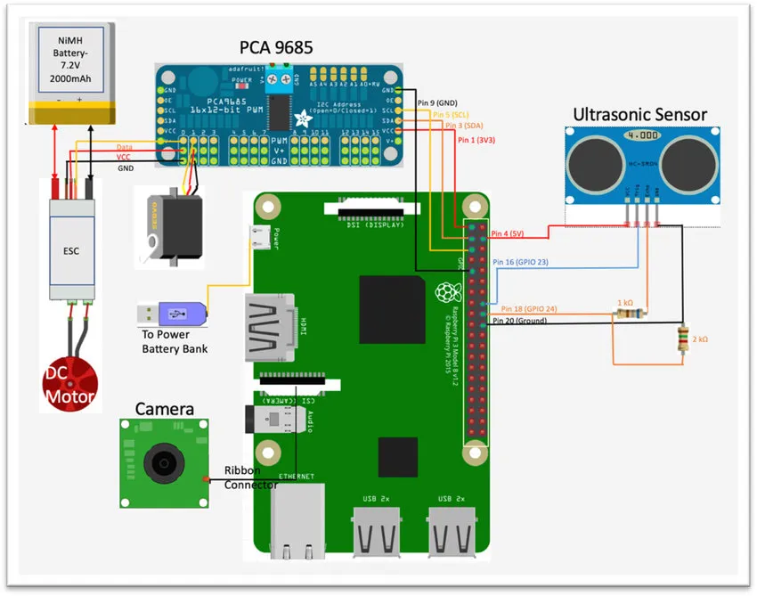
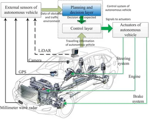
Before jumping into the design process, it's important to understand what an autonomous vehicle control PCB does. This type of PCB acts as the brain of the vehicle, managing critical functions like sensor data processing, motor control, and communication with other systems. For instance, it might handle inputs from LiDAR, ultrasonic sensors, or cameras, process them through a microcontroller or microprocessor, and output signals to actuators or motors for steering, braking, or acceleration.
Key components often found on such a PCB include:
- Microcontroller Unit (MCU) or Microprocessor: Processes data and executes control algorithms.
- Power Management Circuits: Ensures stable voltage and current (e.g., 3.3V or 5V for digital components).
- Sensor Interfaces: Connects to analog or digital sensors with specific impedance matching, often around 50 ohms for high-speed signals.
- Communication Modules: Supports protocols like CAN bus or I2C for data transfer at speeds up to 1 Mbps for CAN in automotive applications.
- Motor Drivers: Controls actuators with current ratings often between 1A to 5A depending on the vehicle's size.
Designing a PCB for these functions requires careful planning to avoid issues like signal interference or power loss, which we'll address using open source PCB design tools.
Choosing the Right Open Source PCB Design Software
When it comes to open source PCB design, several free PCB software options stand out for their features and community support. These tools are perfect for DIY electronics tools and open hardware car control projects. Here are two popular choices that can handle the complexity of autonomous vehicle control designs:
- KiCad: A widely-used, free suite for schematic capture and PCB layout. It supports Windows, macOS, and Linux, offering features like 3D visualization and extensive libraries for components. Its active community makes it a great choice for community PCB projects, where you can find shared designs and advice.
- LibrePCB: A newer option focused on ease of use and cross-platform compatibility. It includes modern features like assembly variant management and production data generation, ideal for streamlining the design of complex boards for autonomous systems.
Both tools are free and provide the flexibility needed for custom designs. For this guide, we'll focus on general steps that apply to most open source tools, ensuring you can adapt the process to your preferred software.
Step-by-Step Guide to Designing Your PCB with Open Source Software
Now that you’ve chosen your software, let’s walk through the process of designing a PCB for autonomous vehicle control. This step-by-step guide will help you navigate the challenges of open source PCB design and create a functional board for your project.
Step 1: Define Your Requirements
Start by listing the specific needs of your autonomous vehicle control system. Consider the following:
- What sensors will you use? (e.g., ultrasonic sensors requiring 5V input)
- What is the processing power needed? (e.g., an MCU with at least 80 MHz clock speed for real-time control)
- What communication protocols are required? (e.g., CAN bus for vehicle networking)
- What are the power requirements? (e.g., a 12V input stepped down to 3.3V for digital circuits)
Having a clear list ensures your design meets all functional needs and avoids costly revisions later.
Step 2: Create a Schematic Diagram
Using your chosen free PCB software, begin with a schematic diagram. This is a blueprint of how components connect electrically. Place your MCU, power circuits, sensor interfaces, and communication modules on the schematic editor. Ensure you account for signal integrity by adding decoupling capacitors (typically 0.1 μF near each IC power pin) to reduce noise.
For an autonomous vehicle PCB, you might include a CAN transceiver for communication, ensuring the signal lines are designed with proper termination resistors (usually 120 ohms at each end of the bus) to prevent signal reflection at speeds up to 1 Mbps.
Step 3: Design the PCB Layout
Once your schematic is complete, move to the PCB layout phase. This step involves placing components on a virtual board and routing the connections. Follow these best practices for an effective layout:
- Component Placement: Group related components (e.g., place sensor interfaces near the MCU to minimize trace length and reduce latency).
- Power and Ground Planes: Use dedicated layers for power (e.g., 12V input) and ground to ensure stable voltage distribution and minimize electromagnetic interference (EMI).
- Signal Routing: Keep high-speed signal traces (like CAN bus lines) short and direct, maintaining a trace width of about 10 mils for 1A current capacity and spacing of at least 8 mils to avoid crosstalk.
- Thermal Management: Add vias under high-power components like motor drivers to dissipate heat, especially if currents exceed 2A.
Most open source PCB design tools offer auto-routing features, but manual routing is recommended for critical paths to ensure optimal performance in autonomous systems.
Step 4: Validate Your Design
Before finalizing, use the design rule check (DRC) feature in your software to identify errors like unconnected nets or clearance violations. For instance, ensure that high-voltage traces (e.g., 12V lines) have at least 15 mils clearance from low-voltage traces (e.g., 3.3V lines) to prevent arcing.
Additionally, simulate signal integrity if your software supports it, checking for issues like overshoot or ringing on high-speed lines. This step is crucial for open hardware car control designs where reliability is paramount.
Step 5: Generate Production Files
Once your design passes validation, generate the necessary files for manufacturing, often called Gerber files. These files include layers for copper, solder mask, and silkscreen. Many open source tools also allow you to export a bill of materials (BOM) to list components for procurement, streamlining the assembly process for your DIY electronics tools project.
Double-check the output files to ensure all layers align correctly, as errors at this stage can lead to manufacturing delays or defective boards.
Best Practices for Autonomous Vehicle Control PCB Design
Designing a PCB for autonomous vehicle control comes with unique challenges. Here are some best practices to ensure your design is robust and reliable:
- Minimize EMI: Use ground planes and shielded traces for sensitive signals to reduce interference, especially near radio frequency (RF) modules if your vehicle uses wireless communication.
- Plan for Scalability: Leave room on the board for future upgrades, such as additional sensor inputs or processing power, by including extra GPIO pins on the MCU.
- Test Iteratively: Build prototypes in stages, starting with a basic power and MCU circuit before adding complex modules like motor drivers. Test each stage for stability (e.g., verify 5V output remains within ±0.1V under load).
- Leverage Community Resources: Engage with online forums and communities around open source PCB design. These groups often share designs and troubleshooting tips for community PCB projects, saving you time and effort.
Challenges and Solutions in Open Source PCB Design for Vehicle Control
While open source software is powerful, it can present challenges, especially for complex projects like autonomous vehicle control. Here are common hurdles and how to overcome them:
- Learning Curve: Tools like KiCad can be intimidating for beginners. Solution: Start with tutorials and sample projects available in the community to build familiarity.
- Limited Libraries: Some components may not be in the default library. Solution: Create custom footprints or download libraries shared by other users in open source communities.
- Performance Constraints: Free software may lack advanced simulation features. Solution: Use external open source simulation tools or focus on manual design checks for critical areas like power distribution.
Tapping Into Community PCB Projects for Inspiration
One of the greatest advantages of open source PCB design is the wealth of community-driven projects. Platforms and forums dedicated to open hardware car control often feature shared designs for autonomous systems, from simple robotic cars to advanced self-driving prototypes. Browsing these projects can provide inspiration and practical solutions for your PCB design.
For instance, you might find open designs for motor control boards that handle 24V inputs with current up to 3A, which you can adapt for your needs. Engaging with these communities also offers opportunities to collaborate or get feedback on your design, enhancing its quality.
Final Thoughts on Building Your Autonomous Vehicle Control PCB
Building a PCB for autonomous vehicle control using open source software is a rewarding endeavor that combines creativity, technical skill, and community collaboration. By leveraging free PCB software, you can design sophisticated boards for open hardware car control without breaking the bank. From defining your requirements to generating production files, each step brings you closer to a functional system that powers your autonomous vehicle.
Remember to prioritize signal integrity, power management, and scalability in your design, and don’t hesitate to tap into the vast resources of community PCB projects for support. With the right approach and DIY electronics tools, your project can achieve professional-grade results, paving the way for innovation in autonomous technology.
At ALLPCB, we're committed to supporting your journey in PCB design and manufacturing. Whether you're a hobbyist or a seasoned engineer, our services are here to help bring your designs to life with precision and efficiency.


