 ALLPCB


In the fast-evolving automotive industry, printed circuit board assemblies (PCBAs) are the backbone of critical systems, from engine control units to advanced driver-assistance systems (ADAS). These components must endure harsh conditions, including extreme temperatures, humidity, and mechanical vibrations, to ensure vehicle safety and reliability. Vibration testing is a vital process to validate the durability of automotive PCBAs, simulating the real-world stresses they face on the road. This blog dives into the key vibration testing standards, methods, and best practices that engineers need to know to design robust PCBAs for automotive applications. Whether you're developing electronics for electric vehicles or heavy-duty trucks, understanding these standards will help you deliver high-quality, reliable products.
Why Vibration Testing Matters for Automotive PCBAs
Vibration testing evaluates how PCB assembly withstands mechanical stresses encountered during vehicle operation. Vibrations from road conditions, engine oscillations, or suspension dynamics can cause failures like cracked solder joints, broken traces, or component detachment. According to a study by the International Organization for Standardization (ISO), rigorous vibration testing can reduce warranty claims by up to 30% by identifying weaknesses early in the design phase. For automotive PCBAs, which often operate in vibration-prone environments, testing ensures functionality and safety under demanding conditions.
Key Vibration Testing Standards for Automotive PCBAs
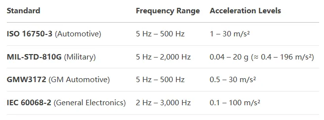
Several industry standards govern vibration testing for automotive PCBAs, providing guidelines on test conditions, frequency ranges, and acceleration levels. Below, we explore the most relevant standards engineers should follow.
ISO 16750-3: Environmental Conditions for Electrical Systems
ISO 16750-3 outlines testing requirements for electrical and electronic systems in road vehicles. For vibration testing, it specifies a frequency range of 10 Hz to 2,000 Hz, with acceleration levels varying based on the component's mounting location (e.g., engine, chassis, or cabin). Test durations can span several hours per axis (X, Y, Z), simulating real-world conditions like potholes or off-road driving. This standard ensures PCBAs can handle the dynamic deflections and stresses encountered during vehicle operation.
MIL-STD-810G: Military-Grade Testing for Harsh Environments
While primarily a military standard, MIL-STD-810G is widely adopted in automotive applications, especially for vehicles designed for rugged environments. It covers vibration testing across a 5 Hz to 2,000 Hz frequency range, with acceleration levels tailored to the component's use case. For example, PCBAs in unsprung locations (e.g., wheel ends) face higher random vibration profiles than those in sprung locations (e.g., cabin). The standard emphasizes random vibration testing to mimic unpredictable road conditions, ensuring structural integrity and reliability.
GMW3172: General Motors' Component Durability Standard
GMW3172, based on IEC 60068-2, is a widely used automotive standard that defines vibration profiles for electrical/electronic components. It specifies sinusoidal and random vibration tests, with acceleration levels up to 20g for engine-mounted PCBAs and lower levels for cabin-mounted ones. The standard includes sine sweep tests to identify resonant frequencies and sine dwell tests to stress components at those frequencies. GMW3172 ensures PCBAs can endure the specific vibration profiles of their intended vehicle mounting location.
IEC 60068-2: Environmental Testing for Electronics
IEC 60068-2 provides a broad framework for environmental testing, including vibration tests for electronics. It includes tests like IEC 60068-2-6 (sinusoidal vibration) and IEC 60068-2-64 (random vibration), with frequency ranges from 5 Hz to 500 Hz and acceleration levels up to 50g, depending on the test condition. This standard is often referenced in automotive testing to ensure PCBAs meet global reliability requirements.
Vibration Testing Methods for Automotive PCBAs
Vibration testing involves subjecting PCBAs to controlled mechanical stresses using specialized equipment like electrodynamic shakers or vibration tables. Here are the primary methods used:
Sinusoidal Vibration Testing
Sinusoidal testing applies a single-frequency vibration with a constant amplitude, simulating repetitive forces like engine oscillations. For example, MIL-STD-883 Method 2007 specifies a sweep from 20 Hz to 2,000 Hz with peak accelerations of 20g, 50g, or 70g, depending on the test condition. This method helps identify resonant frequencies that could lead to fatigue failures in solder joints or components.
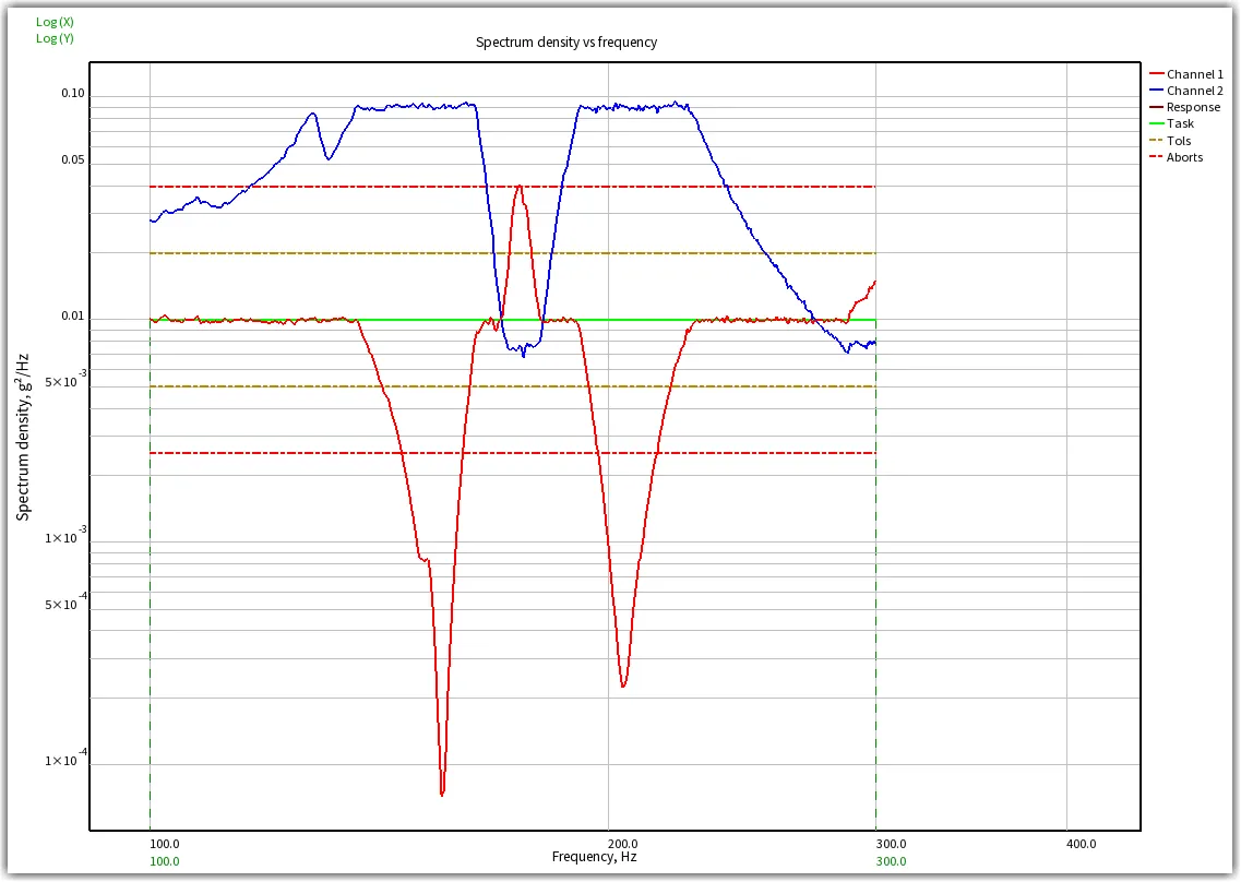
Random Vibration Testing
Random vibration testing replicates the unpredictable vibrations of real-world driving, such as road irregularities or pothole impacts. It uses a power spectral density (PSD) profile to define the vibration energy across a frequency range (e.g., 10 Hz to 500 Hz). GMW3172, for instance, uses PSD plots to simulate vibrations for components in different vehicle locations, ensuring they withstand complex, multi-frequency stresses.
Combined Temperature and Vibration Testing
Automotive PCBAs often face simultaneous thermal and mechanical stresses. Combined testing, as described in IEC 60068-2, subjects PCBAs to vibration while cycling through temperature extremes (e.g., -40°C to 125°C). This approach replicates the harsh conditions of engine compartments, where PCBAs experience both high temperatures and vibrations, ensuring reliability under real-world scenarios.
Best Practices for Effective Vibration Testing
To maximize the effectiveness of vibration testing, engineers should follow these best practices:
1. Characterize Resonance Frequencies
Before testing, perform a modal analysis to identify the PCBA's resonance frequencies. Resonance occurs when the vibration frequency matches the natural frequency of the board, amplifying stresses and causing failures. Tools like laser Doppler vibrometers (LDVs) or accelerometers can measure resonance frequencies, enabling engineers to adjust designs or add damping materials to mitigate risks.
2. Use Realistic Test Profiles
Tailor test profiles to the PCBA's intended vehicle application. For example, engine-mounted PCBAs require higher acceleration levels (e.g., 20g) and sinusoidal profiles, while cabin-mounted ones face lower levels (e.g., 5g) and random vibrations. Using vehicle-specific data, such as PSD plots from road tests, ensures tests accurately simulate real-world conditions.
3. Secure Proper Fixturing
Improper fixturing can introduce unwanted resonances or dampen vibrations, skewing test results. Use rigid fixtures that mimic the PCBA's actual mounting in the vehicle, and verify fixture rigidity with accelerometer tests before starting. This ensures the PCBA experiences the intended vibration profile without external interference.
4. Monitor Failure Modes in Real Time
Use daisy-chained components or real-time resistance monitoring to detect failures like cracked solder joints during testing. This approach, as used in some MIL-STD-810G tests, allows engineers to pinpoint failure modes and assess the PCBA's durability under vibration stress.
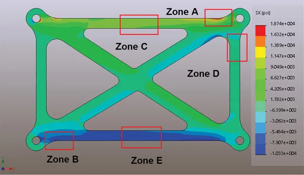
5. Validate with Finite Element Analysis (FEA)
Complement physical testing with FEA to predict vibration responses and optimize designs. FEA models, validated against test data, can simulate stresses on solder joints, traces, and components, reducing the need for costly physical tests. For example, a study on spacecraft PCBAs showed FEA accurately predicted vibration responses, saving time and resources.
Challenges in Vibration Testing for Automotive PCBAs
Despite its importance, vibration testing poses challenges that engineers must address:
- Lack of Universal Standards: Unlike thermal testing, there's no single industry-standard vibration test for PCBAs, leading to variations in test setups and results.
- Complex Failure Modes: Vibrations can cause subtle failures, like micro-cracks in solder joints, which are hard to detect without advanced monitoring.
- Cost and Time Constraints: Comprehensive testing, especially combined temperature and vibration tests, requires significant time and specialized equipment, increasing development costs.
To overcome these, engineers should prioritize standards like ISO 16750-3 or GMW3172, use advanced diagnostic tools, and integrate simulation tools like FEA to streamline testing.
How ALLPCB Supports Automotive PCBA Development
At ALLPCB, we understand the critical role vibration testing plays in automotive PCBA reliability. Our advanced manufacturing capabilities, including quick-turn prototyping and high-precision assembly, enable engineers to iterate designs rapidly and test them against stringent standards like ISO 16750-3 and MIL-STD-810G. With global logistics and a commitment to quality, we deliver PCBAs that meet the automotive industry's demanding requirements, helping you bring reliable, high-performance electronics to market faster.
With globally connected logistics, flexible production volumes, and strict adherence to international quality standards, we are your trusted partner for automotive PCBA solutions. Looking for a fast and competitive PCBA quote? Contact ALLPCB today to streamline your development cycle and accelerate time to market with reliable, high-performance electronic assemblies.
Suggested Reading:Automotive PCBA Conformal Coating Standards
Conclusion
Vibration testing is a cornerstone of automotive PCBA development, ensuring reliability in the face of mechanical stresses. By adhering to standards like ISO 16750-3, MIL-STD-810G, GMW3172, and IEC 60068-2, engineers can validate designs and prevent costly failures. Combining sinusoidal and random vibration tests, using realistic profiles, and leveraging tools like FEA and LDVs enhances testing accuracy and efficiency. At ALLPCB, we're proud to support engineers in creating robust PCBAs that power the future of automotive innovation. By mastering vibration testing, you can deliver electronics that thrive in the toughest conditions, from city streets to off-road trails.


