 ALLPCB


If you're dealing with a malfunctioning PCB assembly, identifying and troubleshooting electronic component failures is crucial to restoring functionality. Whether it's a capacitor shorting out, a resistor burning up, or an IC not responding, understanding the root causes and diagnostic methods can save time and resources. In this comprehensive PCB troubleshooting guide, we'll dive into electronic component failure analysis, covering common capacitor failures, resistor burnout causes, diagnosing IC problems, and SMD component testing. By the end, you'll have actionable steps to pinpoint and resolve issues in your PCB assemblies.
Why Electronic Component Failures Happen in PCB Assemblies
Electronic components in PCB assemblies can fail due to a variety of reasons, including thermal stress, electrical overstress, mechanical damage, and environmental factors. These failures often lead to circuit malfunctions, reduced performance, or complete system breakdowns. According to industry studies, over 60% of PCB failures are linked to component issues caused by improper design, manufacturing defects, or operational stress. Understanding these failure modes is the first step in effective troubleshooting.
In the sections below, we'll break down the most common component failures, their causes, and how to diagnose them using practical techniques. Whether you're an engineer or a hobbyist, these insights will help you tackle issues with precision.

Common Capacitor Failures: Causes and Diagnosis
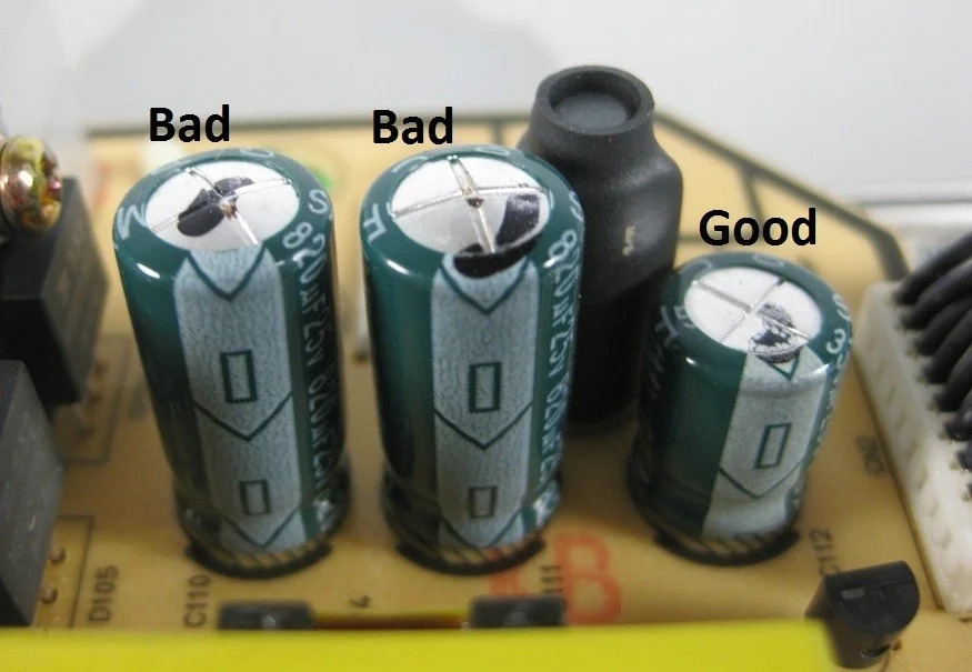
Capacitors are critical for filtering, energy storage, and signal coupling in PCB assemblies, but they are also one of the most failure-prone components. Common capacitor failures include leakage, short circuits, and loss of capacitance. These issues often stem from overvoltage, excessive heat, or poor manufacturing quality.
For instance, electrolytic capacitors can fail due to electrolyte drying out, especially when exposed to temperatures above 85°C for prolonged periods. Ceramic capacitors, on the other hand, may crack under mechanical stress or develop shorts due to manufacturing defects. A study found that nearly 30% of PCB failures in consumer electronics are linked to capacitor issues.
How to Diagnose Capacitor Failures:
- Visual Inspection: Look for bulging, leaking, or cracked capacitors on the PCB. These are clear signs of failure.
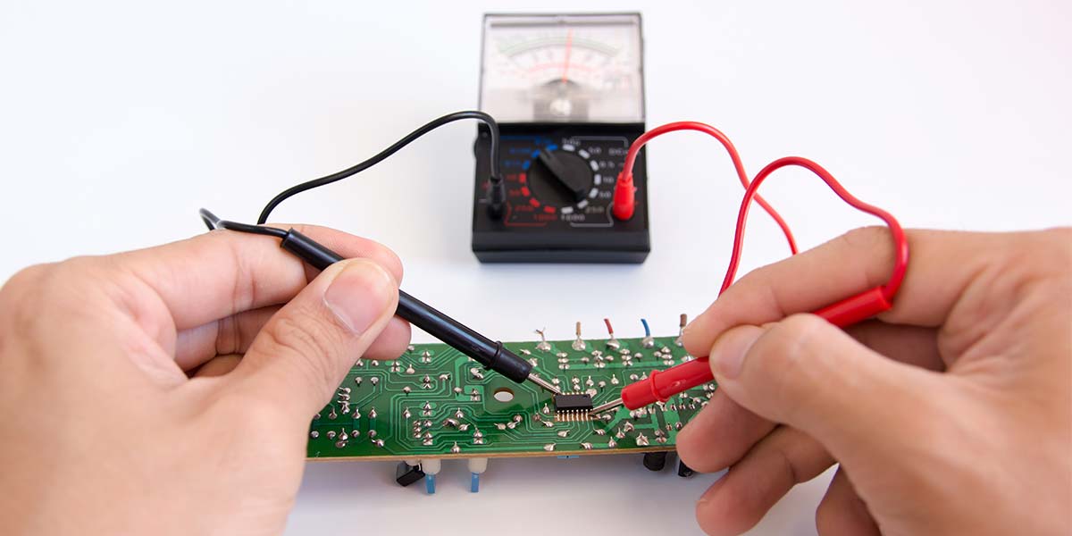
- Multimeter Testing: Set your multimeter to capacitance mode to measure if the value matches the rated specification (e.g., a 10μF capacitor should read close to that value). If it's significantly lower or reads as a short (0 ohms), the capacitor is faulty.
- In-Circuit Testing: Use an ESR (Equivalent Series Resistance) meter to check for high resistance, which indicates degradation, especially in electrolytic capacitors.
Fixing the Issue: Replace faulty capacitors with ones that match the original voltage and capacitance ratings. Ensure proper soldering techniques to avoid further damage.
Resistor Burnout Causes and Troubleshooting Tips
Resistors control current flow and divide voltages in circuits, but they can burn out due to excessive power dissipation, poor design, or environmental factors. Resistor burnout causes include overloading with current beyond their power rating (e.g., a 0.25W resistor handling 0.5W of power will overheat) and prolonged exposure to high temperatures.
Carbon film resistors, for example, can degrade over time if subjected to humidity, leading to changes in resistance values. SMD resistors might fail due to mechanical stress during assembly or thermal cycling.
How to Identify Resistor Burnout:
- Visual Signs: Check for discoloration, charring, or cracks on the resistor body. Burnt resistors often have a distinct smell of charred material.
- Resistance Measurement: Use a multimeter in resistance mode to check if the resistor matches its labeled value (e.g., a 1kΩ resistor should read close to 1000 ohms). An open circuit (infinite resistance) or short (0 ohms) indicates failure.
- Circuit Analysis: Calculate the expected power dissipation using P = I2R. If the actual power exceeds the resistor's rating, it’s likely the cause of burnout.
Preventing Future Failures: Use resistors with higher power ratings for high-current applications and ensure proper heat dissipation through PCB layout design.
Diagnosing IC Problems: Steps to Identify Faulty Integrated Circuits
Integrated Circuits (ICs) are the heart of many PCB assemblies, handling complex functions like processing and signal amplification. Diagnosing IC problems can be challenging due to their complexity, but common issues include internal shorts, open circuits, or logic failures caused by electrostatic discharge (ESD), overvoltage, or thermal stress.
For example, an IC rated for 5V operation might fail if exposed to a 12V spike, damaging internal transistors. Similarly, poor soldering during assembly can lead to cold joints, causing intermittent failures.
Steps for Diagnosing IC Problems:
- Power Supply Check: Use a multimeter to confirm that the IC is receiving the correct voltage at its power pins (e.g., 3.3V or 5V as per the datasheet).
- Signal Testing: Use an oscilloscope to check input and output signals. If a logic IC is supposed to output a 5V square wave at 1MHz but shows no signal or distorted waveform, it may be faulty.
- Thermal Imaging: Use a thermal camera to detect excessive heat from the IC, which could indicate internal shorts or overloading.
- Replacement Testing: If other diagnostics fail, replace the IC with a known good one to see if the issue resolves.
Pro Tip: Always handle ICs with ESD protection to prevent damage during troubleshooting. Use anti-static wrist straps or mats.
SMD Component Testing: Techniques for Surface-Mount Devices
Surface-Mount Devices (SMDs) like resistors, capacitors, and diodes are widely used in modern PCB assemblies due to their compact size. However, their small form factor makes SMD component testing tricky. Failures often occur due to poor soldering, mechanical stress, or thermal cycling during operation.
For instance, an SMD capacitor might fail if a soldering iron applies too much heat, causing internal damage. Similarly, SMD resistors can develop open circuits if the PCB flexes during handling.
How to Test SMD Components:
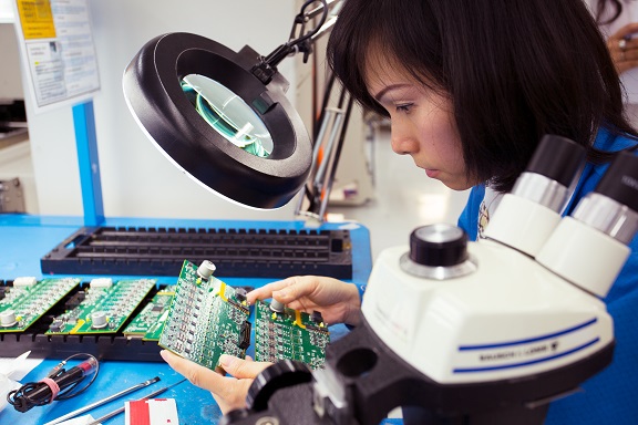
- Visual Inspection with Magnification: Use a magnifying glass or microscope to check for cracked solder joints, misaligned components, or visible damage.
- Continuity Testing: Set a multimeter to continuity mode and probe the SMD pads to check for open or short circuits. Be cautious, as SMD components are delicate.
- Desoldering for Isolated Testing: If in-circuit testing is inconclusive, use a hot air rework station to remove the SMD component and test it separately with a multimeter.
- LCR Meter Use: For SMD capacitors and inductors, an LCR meter can measure inductance, capacitance, and resistance accurately outside the circuit.
Best Practice: Invest in proper tools like fine-tip tweezers and a hot air station for safe handling of SMD components during testing and replacement.
Electronic Component Failure Analysis: A Systematic Approach
Effective electronic component failure analysis requires a structured approach to identify root causes and prevent recurrence. Whether you're dealing with a single failed component or systemic issues in a PCB assembly, follow these steps:
- Document Symptoms: Note down the circuit's behavior, such as no power, intermittent operation, or specific component overheating.
- Isolate the Fault: Use schematic diagrams to trace the signal path and narrow down the problematic area (e.g., power supply section or signal processing stage).
- Test Components: Start with passive components like resistors and capacitors before moving to active components like ICs and transistors.
- Analyze Environmental Factors: Check if the PCB was exposed to extreme temperatures (above 100°C), humidity, or mechanical shock that could contribute to failure.
- Record Findings: Keep a log of failed components, test results, and replacement outcomes to identify patterns in recurring issues.
By following this systematic method, you can reduce troubleshooting time and improve the reliability of your PCB assemblies.
Related Reading: Troubleshooting Active Component Failures in PCBs: A Practical Guide
Preventing Component Failures in PCB Assemblies
While troubleshooting is essential, preventing component failures in the first place is even better. Here are actionable tips to enhance the longevity of your PCB assemblies:
- Design for Reliability: Use components with appropriate voltage, current, and temperature ratings. For example, choose a capacitor rated for 16V if the circuit operates at 12V to provide a safety margin.
- Thermal Management: Incorporate heat sinks or ventilation in your design to keep temperatures below critical thresholds (e.g., under 70°C for most components).
- Quality Components: Source components from reputable suppliers to avoid counterfeit or substandard parts that fail prematurely.
- Proper Assembly: Ensure precise soldering techniques, especially for SMD components, to avoid cold joints or thermal damage.
- Environmental Protection: Use conformal coatings to protect PCBs from moisture and dust, especially in harsh environments.
Implementing these strategies during the design and assembly phases can significantly reduce the likelihood of failures.
Tools You Need for Effective PCB Troubleshooting
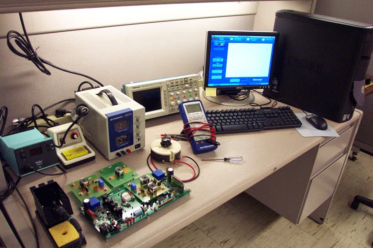
Having the right tools makes troubleshooting faster and more accurate. Here’s a list of essential equipment for diagnosing electronic component failures:
- Digital Multimeter: For measuring voltage, current, resistance, and capacitance.
- Oscilloscope: To analyze signal integrity and waveform issues, especially for ICs.
- ESR Meter: Specifically for testing capacitor health in-circuit.
- Thermal Camera: To detect overheating components without physical contact.
- Hot Air Rework Station: For safely removing and replacing SMD components.
- Magnifying Tools: Such as microscopes or loupes for inspecting small SMD parts.
Investing in these tools ensures you can handle a wide range of troubleshooting scenarios with confidence.
Related Reading: Beyond the Multimeter: Advanced Tools for PCB Fault Diagnosis
Conclusion: Mastering PCB Troubleshooting for Reliable Assemblies
Troubleshooting common electronic component failures in PCB assemblies doesn’t have to be daunting. By understanding the causes behind issues like common capacitor failures, resistor burnout causes, and IC problems, and by mastering techniques such as SMD component testing, you can quickly diagnose and resolve faults. A systematic approach to electronic component failure analysis, coupled with the right tools and preventive measures, ensures your PCB assemblies remain reliable and efficient.
Whether you're fine-tuning a prototype or repairing a production board, the tips and methods in this PCB troubleshooting guide empower you to tackle challenges head-on. Keep learning, stay equipped, and build circuits that stand the test of time.


