ALLPCB


If you're a PCB designer or electrical engineer looking to understand optocouplers, you're in the right place. This guide answers the key question: What are optocouplers, and why are they critical in PCB design? Simply put, optocouplers (or opto-isolators) are electronic components that transfer electrical signals between two isolated circuits using light, ensuring safety and noise reduction. In this comprehensive blog, we'll dive deep into optocoupler basics, their working principle, types, applications in PCB design, and advantages, providing actionable insights for your projects.
Introduction to Optocouplers: Why They Matter in PCB Design
As a PCB designer, you're often tasked with creating circuits that are not only efficient but also safe and reliable. Optocouplers play a vital role in achieving this by providing electrical isolation between different parts of a circuit. Whether you're working on industrial control systems, power supplies, or microcontroller-based designs, understanding optocouplers can elevate your work. They protect sensitive components, reduce noise, and ensure safety by preventing high voltages from damaging low-voltage circuits. Let's explore the fundamentals and see why optocouplers are a go-to solution for many engineers.
Optocoupler Basics: What Are They?
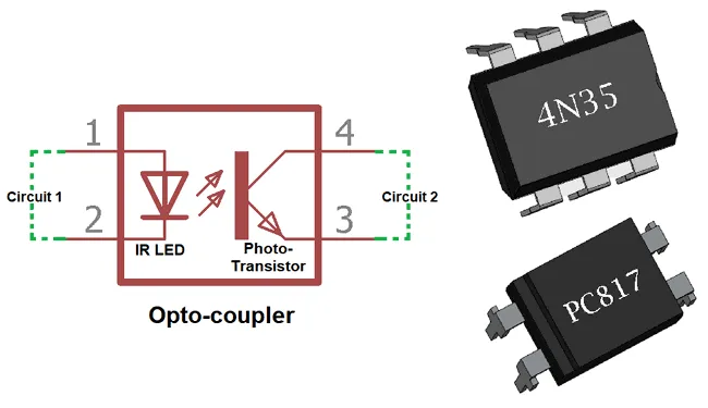
An optocoupler is a small electronic device that uses light to transfer signals between two electrically isolated circuits. It typically consists of a light-emitting diode (LED) on the input side and a photodetector (like a phototransistor or photodiode) on the output side, housed in a single package. The LED converts the input electrical signal into light, which the photodetector then converts back into an electrical signal on the output side. This process ensures no direct electrical connection exists between the two circuits, providing isolation.
For PCB designers, this isolation is crucial. Imagine designing a circuit where a microcontroller operating at 5V needs to communicate with a high-voltage system running at 230V AC. Directly connecting these could fry your microcontroller. An optocoupler steps in to bridge this gap safely, protecting your design and ensuring signal integrity.
Optocoupler Working Principle: How Do They Function?
The working principle of an optocoupler is straightforward yet ingenious. Here's a step-by-step breakdown:
- Input Signal Activation: When an electrical signal is applied to the input side, it powers the LED inside the optocoupler, causing it to emit light.
- Light Transmission: This light travels through an optically transparent medium (often a small gap or optical channel) within the device.
- Output Signal Generation: The light hits the photodetector on the output side, which generates a corresponding electrical signal. For instance, in a phototransistor-based optocoupler, the light causes the transistor to switch on, allowing current to flow.
- Isolation: Since the input and output sides are physically separated and communicate only via light, there’s no electrical connection, providing isolation up to several thousand volts (e.g., 5kV in many standard optocouplers).
This isolation is quantified by the optocoupler’s isolation voltage rating, which indicates the maximum voltage difference it can handle between input and output. Additionally, the Current Transfer Ratio (CTR), typically ranging from 50% to 600%, measures how efficiently the input current translates to output current. For example, a CTR of 100% means a 1mA input current produces a 1mA output current. Understanding these specs helps PCB designers select the right optocoupler for their needs.
Optocoupler Types: Which One Suits Your PCB Design?
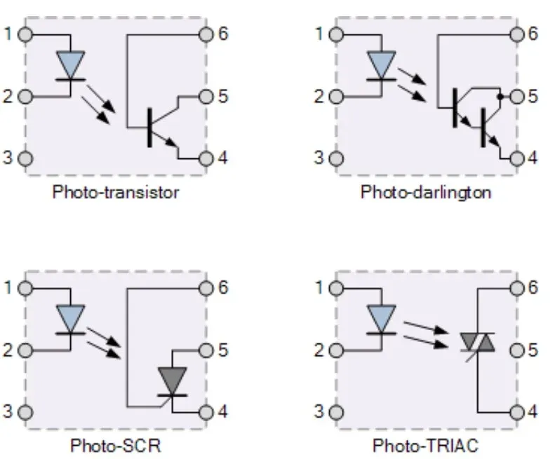
Not all optocouplers are the same. Depending on your application, you’ll need to choose from several types, each with unique characteristics. Here are the most common ones PCB designers encounter:
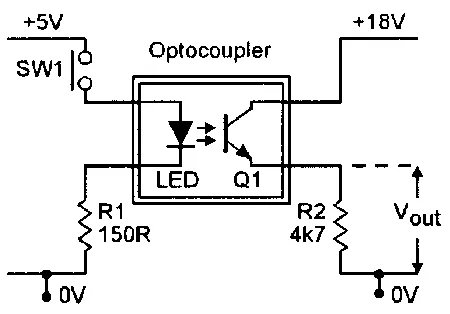
- Phototransistor Optocouplers: These are the most widely used, featuring a phototransistor on the output side. They’re ideal for switching applications, like interfacing microcontrollers with relays. Their response time is moderate, often around 5-10 microseconds.
- Photodiode Optocouplers: These offer faster response times (in the nanosecond range) and are used in high-speed data communication. However, they require external amplification due to their low output current.
- Triac and SCR Optocouplers: Designed for AC power control, these are perfect for switching high-voltage AC loads, such as in dimmer circuits or motor controls. They can handle voltages up to 600V or more.
- Darlington Optocouplers: These provide higher current gain (CTR often above 1000%) due to a Darlington transistor configuration on the output side. They’re great for applications needing high sensitivity but have slower response times.
- High-Speed Optocouplers: Optimized for data rates up to 10 Mbps or higher, these are used in digital communication interfaces like RS-232 or USB isolation.
Choosing the right type depends on factors like speed, voltage, and current requirements. For instance, if you’re designing a PCB for a slow-switching industrial relay system, a phototransistor optocoupler like the popular 4N25 might suffice. For high-speed data transfer, consider a high-speed optocoupler like the HCPL-2631.
Optocoupler Applications in PCB Design: Real-World Uses
Optocouplers are incredibly versatile and find applications across various PCB design scenarios. Here are some key uses that electrical engineers will encounter:
- Signal Isolation: In mixed-signal designs, optocouplers isolate analog and digital sections to prevent noise interference. For example, in audio equipment, they can separate the control circuitry from the power amplifier to avoid ground loops.
- Voltage Level Shifting: They allow communication between circuits with different voltage levels. A common scenario is connecting a 3.3V microcontroller to a 24V industrial sensor without risking damage.
- Power Supply Feedback: In switch-mode power supplies (SMPS), optocouplers like the PC817 provide feedback from the output side to the controller, ensuring stable voltage regulation while maintaining isolation. They can handle isolation voltages up to 5kV, protecting the low-voltage control side.
- Motor Control: Optocouplers drive high-power motors by isolating the control signals from the high-voltage motor drivers, ensuring safety and reliability in industrial automation.
- Medical Equipment: In devices like ECG machines, optocouplers ensure patient safety by isolating the measurement circuit from the main power supply, preventing any risk of electric shock.
As a PCB designer, incorporating optocouplers into your layouts can solve many common challenges. For instance, I recall a project where persistent noise in a sensor circuit was disrupting microcontroller readings. Adding a simple phototransistor optocoupler between the sensor and MCU eliminated the ground noise, saving hours of troubleshooting.
Optocoupler Advantages: Why Use Them in Your Designs?
Optocouplers offer several benefits that make them indispensable for PCB designers and electrical engineers. Here’s why you should consider them for your next project:
- Electrical Isolation: They provide galvanic isolation, protecting sensitive components from high voltages. Isolation ratings often range from 1kV to 7.5kV, depending on the model, ensuring safety in high-voltage environments.
- Noise Reduction: By breaking the electrical connection between circuits, optocouplers eliminate ground loops and reduce electromagnetic interference (EMI), which is critical in high-precision designs.
- Compact Size: Modern optocouplers come in small packages (like DIP-4 or SMD), making them easy to integrate into space-constrained PCB layouts.
- Cost-Effectiveness: Basic optocouplers like the 4N35 are inexpensive, often costing less than $1 per unit, providing a low-cost solution for isolation needs.
- Versatility: With various types available, optocouplers can handle a wide range of applications, from low-speed switching to high-speed data transfer at rates up to 50 Mbps in advanced models.
These advantages translate to safer, more reliable, and efficient designs. For example, in a power supply design, using an optocoupler for feedback not only ensured isolation but also improved the circuit’s response to load changes, maintaining output stability within ±1% of the target voltage.
Key Considerations for Using Optocouplers in PCB Design
While optocouplers are powerful tools, there are a few considerations to keep in mind to ensure optimal performance in your PCB designs:
- Current Transfer Ratio (CTR): Always check the CTR, as it degrades over time (often dropping by 20-30% over a decade). Choose a device with a higher initial CTR to account for this aging effect.
- Response Time: For time-critical applications, ensure the optocoupler’s response time matches your needs. A slow optocoupler (e.g., 10μs) can introduce delays in high-speed systems.
- Layout Placement: Place optocouplers away from heat sources on the PCB, as elevated temperatures can affect their performance and lifespan. Also, ensure proper spacing to maintain isolation integrity.
- Power Consumption: The input LED requires a specific current (often 5-10mA) to operate. Factor this into your power budget, especially in low-power designs.
By addressing these factors, you can avoid common pitfalls. For instance, in a recent PCB layout, I overlooked the CTR degradation of an optocoupler in a long-term industrial application. After a year, the signal strength dropped, requiring a redesign with a higher CTR model. Learning from such experiences can save time and resources.
Conclusion: Mastering Optocouplers for Better PCB Designs
Optocouplers are a cornerstone of modern PCB design, offering isolation, noise reduction, and versatility for a wide range of applications. By understanding optocoupler basics, their working principle, types, applications in PCB design, and advantages, you can make informed decisions that enhance the safety and performance of your circuits. Whether you're isolating a microcontroller from a high-voltage system or reducing noise in a sensitive analog circuit, optocouplers provide a reliable solution.