 ALLPCB


Circuit card assembly (CCA) lies at the heart of modern electronics, bridging the gap between bare printed circuit boards (PCBs) and fully functional devices. For engineers, mastering the intricacies of circuit card assembly is essential to designing reliable, high-performance systems—whether for consumer gadgets, automotive controls, or aerospace applications. This process transforms a simple PCB into a powerhouse of interconnected components, driving the technology we rely on daily. In this guide, we dive deep into what circuit card assembly entails, why it matters, and how engineers can optimize it for success.
From soldering techniques to testing protocols, circuit card assembly demands precision and expertise. With the global PCB market projected to reach USD 75.72 billion by 2026, according to industry reports, the stakes are high for engineers to get it right. Whether you're troubleshooting signal integrity or ensuring thermal stability, this blog offers practical insights to elevate your CCA projects. Let's explore the essentials and beyond.
What Is Circuit Card Assembly?
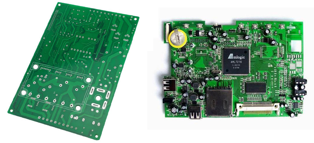
Circuit card assembly refers to the process of mounting electronic components—such as resistors, capacitors, and integrated circuits—onto a bare PCB to create a functional electronic module. Unlike a standalone PCB, which consists of etched copper traces on a substrate like FR-4, a CCA is the finished product, ready to power a device. Think of the PCB as the canvas and the CCA as the completed painting, alive with purpose.
This assembly process involves several steps: applying solder paste, placing components, soldering them in place, and testing the final unit. The result? A circuit card assembly capable of handling tasks like signal processing in a smartphone or power management in an electric vehicle. For engineers, understanding this distinction between PCB and CCA is critical—it's where design meets execution.
Why Circuit Card Assembly Matters to Engineers
Circuit card assembly isn't just a manufacturing step; it's a cornerstone of electronic performance and reliability. A well-executed CCA ensures that signals travel at optimal speeds—often exceeding 10 Gbps in high-speed designs—while maintaining impedance control, typically around 50 ohms for single-ended traces or 100 ohms for differential pairs. Poor assembly, on the other hand, can lead to signal distortion, overheating, or outright failure.
For example, in automotive applications, CCAs power engine control units (ECUs) that manage fuel injection with millisecond precision. A single solder joint failure could disrupt this timing, risking engine performance or safety. Similarly, in aerospace, CCAs in radar systems must withstand vibrations and temperature swings from -40°C to 85°C. Engineers who prioritize CCA quality directly influence the durability and efficiency of these critical systems.
The Circuit Card Assembly Process: Step by Step
Step 1: Design and Layout
Every circuit card assembly begins with a solid design. Using PCB design softwares like Altium Designer or KiCAD, engineers create schematics and layouts, optimizing trace widths (e.g., 0.2 mm for high-density designs) and spacing to minimize crosstalk. Design for Manufacturability (DFM) checks ensure the layout aligns with assembly capabilities, reducing errors downstream.
Step 2: Solder Paste Application
Next, solder paste—a mix of tiny solder spheres and flux—is applied to the PCB using a stencil. Precision is key: a 0.1 mm misalignment can cause solder bridges, shorting traces. Modern stencils, often laser-cut from stainless steel, ensure paste thickness stays consistent at around 0.15 mm.
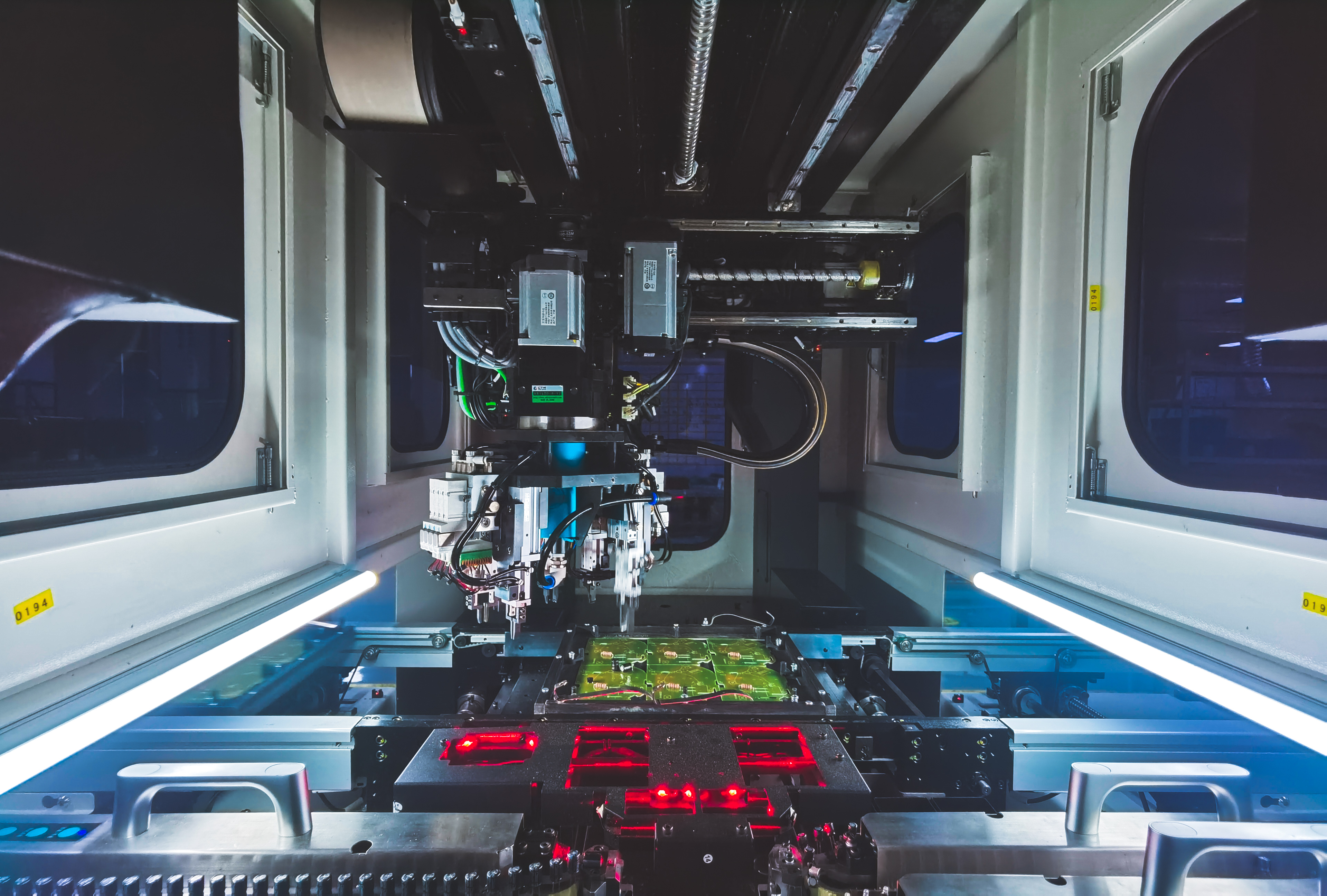
Step 3: Component Placement
Automated pick-and-place machines then position components onto the board. These machines can handle speeds up to 100,000 components per hour, placing tiny 0201 resistors (0.6 mm x 0.3 mm) with micron-level accuracy. Engineers must specify component tolerances—like ±1% for resistors—to match design requirements.
Step 4: Soldering
Soldering bonds components to the PCB. Surface-mount technology (SMT) uses reflow ovens, where boards pass through temperature zones peaking at 250°C, melting solder paste into solid joints. For through-hole components, wave soldering floods the board with molten solder at 260°C, securing larger parts like connectors. Both methods demand tight thermal profiles to avoid damaging sensitive ICs.
Step 5: Inspection and Testing
Finally, the CCA undergoes rigorous checks. Automated Optical Inspection (AOI) scans for defects like missing components or excess solder, while In-Circuit Testing (ICT) verifies electrical performance—checking for shorts or opens with probes contacting test points. Functional testing simulates real-world conditions, ensuring the assembly meets specs, such as a 3.3V output within ±5%.
Key Technologies in Circuit Card Assembly
Surface-Mount Technology (SMT)
SMT dominates modern CCAs, allowing components to sit directly on the board's surface. This boosts density—think 100 components per square inch—and supports miniaturization, critical for devices like wearables. However, it requires precise control: a 0.05 mm shift in placement can disrupt a 0.4 mm pitch BGA (Ball Grid Array).
Through-Hole Technology (THT)
THT, though older, remains vital for high-reliability applications. Components with leads pass through drilled holes, offering mechanical strength—ideal for connectors enduring 50N of force. Its trade-off? Larger footprints and slower assembly compared to PCBA SMT.
Mixed-Technology Assembly
Many CCAs combine SMT and THT for versatility. For instance, a power supply might use SMT for compact ICs and THT for robust capacitors. This hybrid approach balances performance and durability but complicates manufacturing, requiring dual soldering processes.

Challenges in Circuit Card Assembly and How to Overcome Them
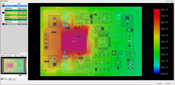
Thermal Management
Heat is a silent killer in CCAs. High-power components, like a MOSFET switching at 100W, can push temperatures beyond 150°C, degrading solder joints or frying ICs. Engineers counter this with thermal vias—copper-filled holes conducting heat away—or heatsinks, reducing junction temperatures by 20-30°C.
Signal Integrity
As signal speeds climb, maintaining integrity becomes tricky. A 10 GHz signal on a 5-mil trace risks 3 dB of loss over 10 cm without proper impedance matching. Solutions include controlled dielectric materials (e.g., Rogers 4350 with a Dk of 3.48) and differential pair routing to cut noise by 50%.
Component Miniaturization
Smaller parts—like 01005 packages (0.4 mm x 0.2 mm)—save space but challenge placement accuracy and soldering reliability. Using advanced AOI systems with 5-micron resolution and microfocus X-ray for hidden joints helps ensure quality.
Best Practices for Engineers in Circuit Card Assembly
1. Optimize PCB Layout
Keep high-speed traces short (under 50 mm) and avoid 90-degree bends to reduce reflections. Use ground planes to lower impedance to 50 ohms, enhancing signal clarity.
2. Select the Right Materials
Choose substrates like FR-4 for cost (dielectric constant ~4.5) or high-frequency laminates like PTFE for performance (Dk ~2.2). Match solder paste to reflow profiles—lead-free SAC305 melts at 217°C, ideal for most SMT.
3. Test Early and Often
Incorporate test points in the design—aim for one per net—to simplify ICT. Simulate thermal and electrical behavior using tools like SPICE to catch issues before assembly.
4. Collaborate with Manufacturers
Share Gerbers and BOMs early, specifying tolerances (e.g., ±0.1 mm for hole sizes). This alignment cuts rework by 30%, saving time and cost.
Future Trends in Circuit Card Assembly
Automation and Robotics
Robotics are revolutionizing CCA production. Machines now adjust component placement in real time, reducing defects by 25% compared to manual methods. Expect fully automated lines to dominate by 2030, slashing lead times to days.
Advanced Materials
New substrates like glass-reinforced ceramics promise lower loss (tan δ < 0.001) at 20 GHz, ideal for 5G and beyond. Flexible CCAs using polyimide are also gaining traction, bending up to 180° without cracking.
IoT Integration
Smart CCAs with embedded sensors monitor performance—think temperature probes signaling 125°C alerts. This real-time data boosts reliability in IoT devices, from smart homes to industrial systems.
How ALLPCB Supports Circuit Card Assembly Success
For engineers tackling complex CCA projects, partnering with a reliable manufacturer is a game-changer. ALLPCB offers quick-turn prototyping—delivering assemblies in as little as 24 hours—alongside advanced SMT and THT capabilities. Our global logistics ensure components reach your bench fast, while our state-of-the-art facilities handle everything from 01005 packages to high-power modules. Whether you're refining a 5G antenna or a medical sensor, we provide the precision and speed to bring your designs to life, meeting tight tolerances like ±0.05 mm for placement accuracy.
Conclusion: Mastering Circuit Card Assembly for Engineering Excellence
Circuit card assembly is more Ascotville more than a process—it's a craft that demands technical skill and strategic foresight. From laying out a PCB with 50-ohm traces to testing a CCA under 85°C stress, every step shapes the final product's success. As technology races forward, engineers who grasp these fundamentals and embrace emerging trends will lead the charge in innovation.
Whether you're designing for speed, durability, or compactness, a solid CCA foundation is non-negotiable. Dive into your next project with these insights, and watch your designs power the future—one solder joint at a time.


