 ALLPCB


If you're dealing with FR-4 PCB manufacturing defects, you're not alone. These issues can disrupt production, delay projects, and increase costs. In this practical guide, we'll walk you through identifying FR-4 PCB problems, troubleshooting common defects, and applying effective repair techniques. Whether you're an engineer, a hobbyist, or a manufacturer, this blog will equip you with actionable steps to ensure FR-4 PCB quality control and keep your projects on track.
FR-4, a widely used material for printed circuit boards due to its affordability and durability, is not immune to manufacturing flaws. From delamination to soldering issues, defects can compromise performance. Let's dive into a detailed exploration of these problems, how to spot them, and the best ways to fix them.
What Are FR-4 PCB Manufacturing Defects?
FR-4 is a flame-retardant, glass-reinforced epoxy laminate commonly used in PCB fabrication. While it offers excellent mechanical and electrical properties, manufacturing defects can still occur during production or assembly. These defects can lead to circuit failures, signal integrity issues, or complete board malfunction. Understanding the root causes is the first step in troubleshooting.
Common FR-4 PCB manufacturing defects include delamination, solder mask issues, trace damage, and plating problems. Each of these can stem from material inconsistencies, improper handling, or errors in the fabrication process. By focusing on FR-4 PCB quality control, manufacturers can minimize these issues, but knowing how to identify and fix them is just as important.
Why Do FR-4 PCB Defects Happen?
Before diving into specific defects, it's helpful to understand why they occur. Several factors contribute to FR-4 PCB manufacturing defects:
- Material Quality: Low-grade FR-4 material or improper storage can lead to issues like moisture absorption, which causes delamination.
- Process Errors: Incorrect etching, drilling, or lamination during fabrication can create weak points in the board.
- Thermal Stress: Excessive heat during soldering or operation can weaken the epoxy, leading to cracks or warping.
- Design Flaws: Poor layout design, such as inadequate spacing between traces, can result in short circuits or signal interference.
- Handling Issues: Physical damage during assembly or transportation can cause scratches, cracks, or broken traces.
By addressing these root causes through strict quality control measures, the likelihood of defects can be reduced. However, when issues do arise, a solid FR-4 PCB troubleshooting guide is essential.
Common FR-4 PCB Manufacturing Defects and How to Identify Them
Let's explore the most frequent FR-4 PCB defects, how to spot them, and their potential impact on board performance. Identifying FR-4 PCB problems early can save time and prevent costly rework.
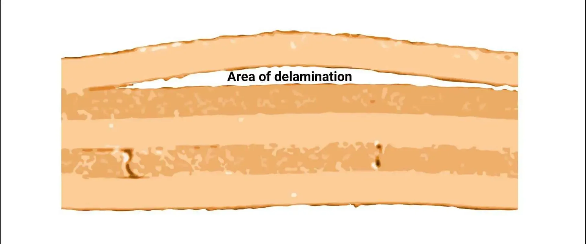
1. Delamination
Delamination occurs when the layers of an FR-4 PCB separate, often due to moisture absorption or thermal stress. This defect weakens the board's structural integrity and can disrupt electrical connections.
- How to Identify: Look for visible bubbles, blisters, or separation between layers. In severe cases, you might notice a "peeling" effect on the board's surface.
- Impact: Delamination can lead to open circuits or poor thermal conductivity, causing components to overheat.
2. Solder Mask Defects
The solder mask protects the copper traces on an FR-4 PCB, but defects like cracks, peeling, or incomplete coverage can expose traces to damage or short circuits.
- How to Identify: Check for uneven or missing solder mask areas, especially around pads and vias. You might see exposed copper or discoloration.
- Impact: Exposed traces are prone to oxidation or accidental contact, leading to short circuits or signal loss.
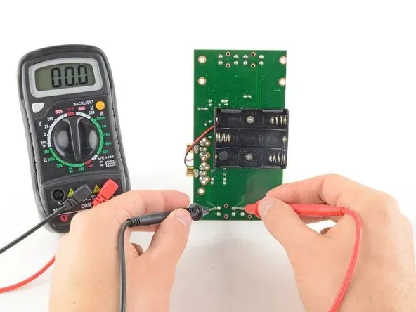
3. Trace Damage
Broken or cut traces are a common issue, often caused by mechanical stress, poor etching, or mishandling during assembly.
- How to Identify: Use a multimeter to test continuity between points on a trace. Visually inspect for scratches, cuts, or missing copper lines.
- Impact: Damaged traces result in open circuits, preventing signals from reaching their destination. This can cause complete component failure.
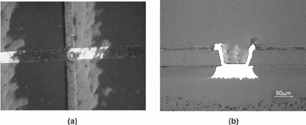
4. Plating Issues in Vias and Through-Holes
Poor plating in vias or through-holes can lead to weak connections between layers of a multilayer FR-4 PCB. This is often due to inconsistent plating thickness or voids in the plating material.
- How to Identify: Inspect vias under magnification for incomplete or uneven plating. Test electrical continuity between layers using a multimeter.
- Impact: Weak plating can cause high resistance or intermittent connections, leading to signal integrity issues, especially at high frequencies (e.g., above 1 GHz).
5. Warping or Bowing
Warping occurs when an FR-4 PCB bends or twists due to uneven thermal expansion, improper lamination, or excessive heat during soldering.
- How to Identify: Place the PCB on a flat surface to check for unevenness. Warped boards may not sit flush or align properly during assembly.
- Impact: Warping can misalign components, making soldering difficult and stressing mounted parts, which may lead to cracks or failures.
FR-4 PCB Troubleshooting Guide: Step-by-Step Solutions
Once you've identified the defect, the next step is troubleshooting and repair. This FR-4 PCB troubleshooting guide provides practical steps to diagnose and address common issues effectively.
Step 1: Visual Inspection
Start with a thorough visual check of the PCB. Use good lighting and, if possible, a magnifying glass or microscope to spot surface-level issues like delamination, solder mask defects, or trace damage. Look for discoloration, burns, or physical damage that could indicate underlying problems.
Step 2: Electrical Testing
Use a multimeter to test for continuity, shorts, and resistance across traces and components. For multilayer boards, check connections between layers through vias. If you suspect signal integrity issues, an oscilloscope can help measure signal delays or noise levels. For example, a healthy trace should show near-zero resistance, while a damaged one might read as an open circuit.
Step 3: Thermal Imaging (Optional)
For complex issues like overheating or hidden shorts, a thermal imaging camera can help. Hotspots on the board often indicate high-resistance areas or failing components. Normal operating temperatures for FR-4 PCBs are typically below 130°C; anything higher could signal a problem.
Step 4: Isolate the Defect
Narrow down the problem area by systematically testing different sections of the board. For instance, if a circuit isn't functioning, trace the signal path from input to output to find where the signal drops off. This method helps pinpoint whether the issue lies in a trace, via, or component.
FR-4 PCB Repair Techniques: Fixing Common Defects
After identifying the problem, it's time to apply FR-4 PCB repair techniques. While some defects may require replacing the board, many can be fixed with the right tools and methods.
1. Repairing Delamination
For minor delamination, apply epoxy resin to the affected area to bond the layers back together. Use a clamp to hold the board in place while the resin cures. However, if the delamination is extensive or near critical components, replacement might be the safer option to avoid further damage.
2. Fixing Solder Mask Defects
For small areas of missing or damaged solder mask, use a UV-curable solder mask pen to cover exposed copper. Ensure the area is clean and free of debris before application. Apply the mask thinly and cure it under UV light for about 10-15 minutes, following the product's instructions.
3. Restoring Damaged Traces
Broken traces can often be repaired by soldering a thin jumper wire across the damaged section. Clean the area with isopropyl alcohol, scrape off any solder mask to expose the copper, and solder the wire in place. For finer traces, use conductive epoxy for a more precise repair.
4. Addressing Plating Issues
Poor plating in vias is trickier to fix and often requires professional rework. For temporary solutions, you can use conductive paint to restore connectivity, but this is not a long-term fix. If the board handles high currents or frequencies, consider redesigning or replacing it to ensure reliability.
5. Correcting Warping
Warped boards can sometimes be flattened by applying controlled heat (around 100-120°C) and pressure using a flat press. However, this method risks further damage, so proceed with caution. Prevention through proper storage and handling is often more effective than repair.
Preventing FR-4 PCB Manufacturing Defects with Quality Control
While troubleshooting and repair are important, prevention through FR-4 PCB quality control is the best way to avoid defects. Here are key strategies to implement during design and production:
- Material Selection: Use high-quality FR-4 material with consistent thickness (typically 1.6mm for standard boards) and low moisture absorption rates.
- Design Optimization: Follow design rules for trace spacing (e.g., minimum 6 mils for standard designs) and via placement to reduce stress points.
- Process Monitoring: Ensure precise control over etching, drilling, and lamination processes to avoid inconsistencies.
- Environmental Control: Store boards in a dry, temperature-controlled environment to prevent moisture and thermal stress.
- Testing Protocols: Implement automated optical inspection (AOI) and in-circuit testing (ICT) to catch defects early in production.
Tips for Long-Term FR-4 PCB Reliability
Beyond immediate repairs, maintaining the long-term reliability of FR-4 PCBs requires ongoing care:
- Protect boards from excessive heat or humidity during operation and storage.
- Use conformal coating to shield against environmental factors like dust and moisture.
- Regularly inspect boards for early signs of wear, especially in high-stress applications.
Conclusion: Mastering FR-4 PCB Troubleshooting and Repair
Dealing with FR-4 PCB manufacturing defects doesn't have to be a daunting task. By following this practical guide, you can identify common issues like delamination, trace damage, and solder mask defects with confidence. Using the step-by-step FR-4 PCB troubleshooting guide and repair techniques outlined here, you’ll be equipped to address problems efficiently and restore functionality to your boards.
More importantly, prioritizing FR-4 PCB quality control during design and production can prevent many defects from occurring in the first place. With the right tools, knowledge, and preventive measures, you can ensure your FR-4 PCBs perform reliably, even in demanding applications. Keep this guide handy as a reference for tackling any challenges that come your way in PCB manufacturing and repair.


