ALLPCB


If you’re diving into the world of security camera design or repair, understanding a security camera PCB schematic is a crucial first step. A PCB (Printed Circuit Board) schematic is essentially a blueprint that shows how components in a CCTV camera are connected. In this detailed tutorial, we’ll break down the basics of reading security camera PCB layouts, explain CCTV circuit diagrams, and guide you through understanding camera PCB components. Whether you’re into DIY electronics or looking to master security camera schematics, this step-by-step guide will help you navigate the process with ease.
Let’s explore everything from the fundamental concepts to practical tips for interpreting and working with these designs. By the end, you’ll have a solid grasp of how these circuits work and how to apply this knowledge in real-world projects.
What Is a Security Camera PCB Schematic?
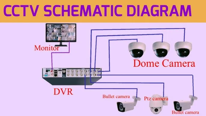
A security camera PCB schematic is a detailed diagram that maps out the electrical connections between components on a printed circuit board used in surveillance cameras. It acts as a guide for engineers and hobbyists to understand how power, signals, and data flow within the device. These schematics are critical for designing, troubleshooting, or repairing CCTV systems.
In simple terms, the schematic shows you where each part—like the image sensor, power regulator, or video output chip—fits into the circuit. It also highlights connections, such as how a 12V power input is stepped down to 3.3V for specific components. Whether you’re building a DIY electronics security camera or analyzing an existing design, mastering these diagrams is key.
Why Understanding CCTV Circuit Diagrams Matters
CCTV circuit diagrams provide insight into how a security camera operates at its core. By learning to read these layouts, you can identify issues like a faulty power supply (common in cameras failing to boot) or a damaged image sensor (leading to poor video quality). This knowledge is invaluable for:
- Designing custom security camera systems.
- Repairing malfunctioning devices by tracing signal paths.
- Enhancing existing setups with modifications like night vision capabilities.
For DIY enthusiasts, understanding camera PCB components also opens doors to creative projects, such as integrating cameras with smart home systems.
Key Components of a Security Camera PCB
Before diving into reading security camera PCB layouts, let’s break down the core components you’ll encounter on a typical board. Each part plays a specific role in capturing, processing, and transmitting video footage.
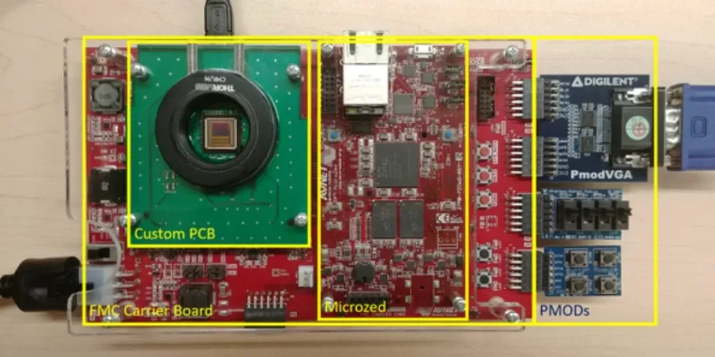
1. Image Sensor
The image sensor, often a CMOS or CCD chip, is the heart of the camera. It converts light into electrical signals to create video or images. For example, a common CMOS sensor might operate at 3.3V and output data at a rate of 30 frames per second for 1080p resolution.
2. Power Management Circuit
This section regulates the input voltage (typically 12V DC for most CCTV cameras) and steps it down to lower voltages like 5V or 3.3V for different chips. A typical power IC might handle a current of up to 1A to ensure stable operation.
3. Microcontroller Unit (MCU)
The MCU processes signals from the image sensor and manages features like motion detection or video compression. It often runs at a clock speed of 100 MHz or higher in modern cameras for efficient processing.
4. Video Output Module
This component converts processed data into a transmittable format, such as analog (CVBS) or digital (IP over Ethernet). Impedance matching at 75 ohms is crucial here for analog outputs to prevent signal loss.
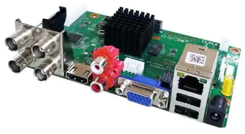
5. Connectors and Ports
These include power jacks, video output ports, and sometimes network connectors for IP cameras. Proper layout ensures minimal interference, especially for high-speed data lines.
Step-by-Step Guide to Reading Security Camera PCB Schematics
Now that you’re familiar with the components, let’s walk through a step-by-step process for reading and interpreting a security camera PCB schematic. This guide is tailored for beginners and intermediate enthusiasts in DIY electronics security camera schematics.
Step 1: Identify the Power Supply Section
Start by locating the power input on the schematic, usually marked with a symbol for a DC source or labeled as “VIN.” Trace the lines to see how voltage is distributed. Look for components like voltage regulators (e.g., a 7805 IC for 5V output) or capacitors (often 10μF or 100μF) that stabilize the power. Understanding this section helps ensure the camera receives the correct voltage without spikes that could damage sensitive parts.
Step 2: Locate the Image Sensor and Signal Path
Find the image sensor, typically represented by a rectangular block with pins for power, ground, and data output. Follow the data lines to see how they connect to the MCU or video processor. Signal paths often include resistors or filters to reduce noise, ensuring clear video output at speeds like 27 MHz for standard HD signals.
Step 3: Check the Video Output Circuit
Trace the output from the processor to the video port. For analog cameras, you’ll see a 75-ohm resistor near the output to match impedance with coaxial cables. For IP cameras, look for Ethernet transformers or RJ45 connectors. This step is crucial for understanding how video data leaves the camera.
Step 4: Examine Supporting Circuits
Look for additional features like infrared (IR) LEDs for night vision, controlled by transistors or dedicated ICs. These circuits might activate based on a light sensor input, drawing around 200mA per LED array. Identifying these extras helps you understand the camera’s full functionality.
Step 5: Review Grounding and Noise Reduction
Pay attention to ground planes (marked as “GND”) and decoupling capacitors near ICs. These prevent interference in high-frequency circuits, ensuring stable operation. Poor grounding can lead to video artifacts or flickering, so this is a critical aspect of any design.
Common Challenges in Understanding Camera PCB Components
Reading security camera PCB layouts can be tricky, especially for beginners. Here are some common hurdles and how to overcome them:
1. Complex Diagrams
Some schematics include dozens of components and connections, making them hard to follow. Break them down into smaller sections, starting with power, then moving to signal flow. Use a highlighter or digital tool to trace paths one at a time.
2. Unfamiliar Symbols
Circuit symbols for diodes, transistors, or ICs might be new to you. Keep a reference chart handy or use online resources to decode them. Most schematics also include a legend or component list.
3. Missing Specifications
Not all schematics provide details like voltage ratings or resistor values (e.g., 1kΩ). In such cases, cross-reference with datasheets for the listed components or measure them directly on a physical board if available.
Tips for Designing Your Own Security Camera PCB Schematic
If you’re venturing into DIY electronics security camera schematics, designing a PCB from scratch is an exciting challenge. Here are practical tips to get started:
1. Start with a Block Diagram
Before drawing a full schematic, sketch a block diagram outlining major sections like power, sensor, processor, and output. This simplifies the process and ensures you don’t miss key elements.
2. Use Standard Design Software
Leverage PCB design tools to create accurate schematics. These tools often include libraries with pre-built components for security cameras, saving time and reducing errors.
3. Optimize for Signal Integrity
Place high-speed components like the image sensor close to the processor to minimize signal delay. Keep power lines short and wide to handle currents up to 2A without voltage drops.
4. Test Incrementally
Build and test small sections of your circuit before assembling the full PCB. For instance, verify that the power circuit outputs a stable 3.3V before connecting the sensor.
Practical Applications of CCTV Circuit Diagrams Explained
Understanding CCTV circuit diagrams isn’t just academic—it has real-world uses. For instance, technicians use schematics to diagnose why a camera isn’t recording, often finding issues like a blown fuse in the power line. Hobbyists might modify a camera to support higher resolution by upgrading the sensor, using the schematic to ensure compatibility with existing circuits.
In professional settings, engineers rely on these diagrams to design systems for specific environments, like outdoor cameras with weatherproofing circuits drawing minimal power (under 5W) to save energy. Whatever your goal, a solid grasp of schematics empowers you to innovate and solve problems effectively.
Troubleshooting Using Security Camera PCB Schematics
When a security camera fails, a schematic is your best friend for troubleshooting. Here’s a quick guide:
- No Power: Check the power input and regulator for issues. Measure voltage at key points to ensure it matches the expected 12V or 5V.
- Poor Video Quality: Inspect the image sensor and signal path for loose connections or damaged components. Look for noise filters or capacitors that might be faulty.
- No Output: Trace the video output circuit to ensure the signal reaches the connector. Test impedance at the output port for mismatches.
Using a multimeter, you can verify voltages and continuity based on the schematic, pinpointing failures with precision.
Resources for Learning More About Security Camera PCB Layouts
If you’re eager to deepen your knowledge of reading security camera PCB layouts, consider these resources:
- Online tutorials and forums dedicated to electronics and CCTV systems.
- Datasheets for common camera components like CMOS sensors or video encoders.
- Free or paid courses on circuit design tailored to surveillance technology.
Hands-on practice with actual boards and schematics will also accelerate your learning. Start with simple analog cameras before moving to complex IP systems.
Conclusion: Mastering Security Camera PCB Schematics
Understanding security camera PCB schematics is a powerful skill for anyone interested in surveillance technology or DIY electronics. From identifying key components like the image sensor to tracing signal paths and troubleshooting issues, this step-by-step tutorial has covered the essentials of reading and designing CCTV circuit diagrams. With practice, you’ll gain confidence in interpreting complex layouts and applying your knowledge to real-world projects.
Whether you’re a hobbyist building a custom camera or a professional optimizing a security system, the ability to decode and create schematics will set you apart. Keep exploring, testing, and learning to stay ahead in this ever-evolving field. For high-quality PCB manufacturing and design support, trust our expertise to bring your security camera projects to life.