 ALLPCB


If you're facing issues with your DIY router or switch PCB, such as shorts, open circuits, or erratic performance, you're not alone. Many hobbyists and engineers encounter these problems during the design and assembly process. The good news? Most of these issues can be resolved with systematic troubleshooting. In this guide, we'll walk you through common problems like shorts and open circuits, provide actionable solutions for debugging your PCB, and help you get your project back on track.
Whether you're a beginner or an experienced maker, troubleshooting a DIY PCB for a router or switch can be challenging but rewarding. This blog dives deep into identifying and fixing router switch issues, ensuring your board functions as intended. Let's explore the most common problems and their solutions step by step.
Why Troubleshooting Your DIY PCB Matters
Creating a DIY PCB for a router or switch is a complex task that involves designing circuits, soldering components, and testing functionality. Even a small error in design or assembly can lead to significant issues, such as data loss, dropped connections, or complete failure of the board. Troubleshooting helps you pinpoint these problems, save time, and avoid costly redesigns. By mastering debugging techniques, you can ensure your DIY project performs reliably, whether it's for personal use or a professional prototype.
Common Issues in DIY Router/Switch PCBs
Before diving into solutions, it's important to understand the typical problems that arise when working on a DIY PCB for networking devices like routers and switches. Below are some of the most frequent issues you might encounter.
1. Shorts (Short Circuits)
A short circuit happens when two points in a circuit that shouldn't be connected come into contact, often due to stray solder, misplaced components, or design errors. In a router or switch PCB, shorts can cause excessive current flow, overheating, or even permanent damage to components.
- Symptoms: Overheating components, burning smells, or a complete power failure.
- Common Causes: Solder bridges between pads, incorrect component placement, or manufacturing defects in the board.
2. Open Circuits
An open circuit occurs when there's a break in the electrical path, preventing current from flowing. This can result in parts of your router or switch not functioning, such as a port failing to transmit data.
- Symptoms: Non-functional sections of the board, such as a specific Ethernet port not working.
- Common Causes: Broken traces, poor soldering, or damaged components.
3. Signal Integrity Issues
Signal integrity problems are common in high-speed devices like routers and switches, where data signals must travel at speeds often exceeding 1 Gbps. Issues such as crosstalk or impedance mismatch can degrade performance.
- Symptoms: Slow data transfer rates, frequent packet loss, or intermittent connectivity.
- Common Causes: Poor trace routing, incorrect impedance matching (target impedance for high-speed signals is often around 50 ohms), or interference from nearby traces.
4. Power Supply Problems
Routers and switches require stable power delivery to function correctly. Fluctuations or insufficient power can cause erratic behavior or failure to boot.
- Symptoms: Board fails to power on, random resets, or dim LEDs.
- Common Causes: Incorrect voltage input (e.g., supplying 12V when the board requires 5V), faulty regulators, or inadequate decoupling capacitors.
Step-by-Step Guide to Debugging Your DIY PCB
Now that you know the common issues, let's walk through a systematic approach to troubleshooting your DIY router or switch PCB. These steps will help you identify and resolve problems efficiently.
Step 1: Visual Inspection
Start with a thorough visual check of your PCB. Many issues, such as shorts or open circuits, can be spotted with the naked eye or a magnifying glass.
- Look for solder bridges between pads or pins.
- Check for cracked or damaged traces on the board.
- Ensure all components are placed correctly and oriented as per the schematic.
Tip: Use good lighting and a magnifying tool to inspect small components like SMD resistors or capacitors, which are often less than 1mm in size.
Step 2: Test for Shorts and Open Circuits
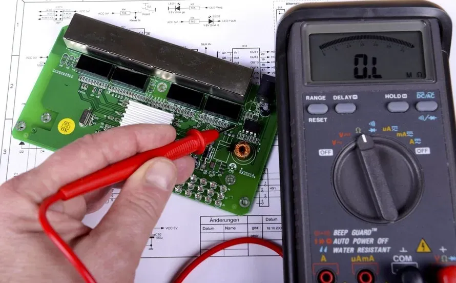
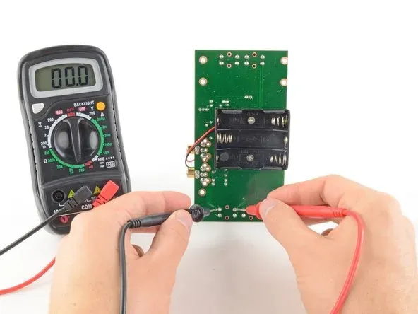
Use a multimeter in continuity mode to test for shorts and open circuits. This is one of the most effective ways to debug a PCB.
- For Shorts: Set the multimeter to continuity mode and probe between adjacent pins or traces. If you hear a beep where there shouldn't be a connection, you've found a short.
- For Open Circuits: Test along a trace or between a component and its connected pad. If there's no continuity where there should be, you have an open circuit.
Step 3: Verify Power Supply
Ensure your board is receiving the correct voltage and current. Most router or switch PCBs operate at voltages between 3.3V and 12V, depending on the design.
- Use a multimeter to measure voltage at key points, such as the input pin of a voltage regulator or the power pins of an IC.
- Check if decoupling capacitors (typically 0.1μF to 10μF) are placed near ICs to stabilize the power supply.
Tip: If the voltage is lower than expected (e.g., 4.5V instead of 5V), check for overloaded circuits or faulty regulators.
Step 4: Analyze Signal Integrity
For high-speed designs like routers, signal integrity is critical. Use an oscilloscope to inspect signal waveforms if you suspect issues.
- Look for overshoot or ringing in signals, which can indicate impedance mismatch. High-speed traces should ideally have a controlled impedance of 50 ohms.
- Check for crosstalk by observing if nearby traces are interfering with each other.
Tip: If you don't have an oscilloscope, minimize signal issues by following best practices in your design, such as keeping high-speed traces short (under 10cm if possible) and avoiding sharp bends.

Step 5: Test Functionality Incrementally
Instead of testing the entire board at once, break it down into smaller sections. For a router PCB, test individual ports or the power supply circuit first before moving to data transmission.
- Power on the board and check if LEDs light up as expected.
- Connect a single Ethernet cable to test data transfer on one port before testing all ports.
Solutions for Common Router/Switch PCB Issues
Once you've identified the problem, it's time to apply the right solution. Below are targeted fixes for the issues discussed earlier.
Fixing Shorts
- Remove Solder Bridges: Use a desoldering wick or pump to remove excess solder between pads. Apply flux to make the process easier.
- Re-check Component Placement: Ensure no pins are touching where they shouldn't. If necessary, re-solder with precision.
Repairing Open Circuits
- Bridge Broken Traces: If a trace is visibly damaged, use a small piece of wire or conductive paint to reconnect it. Secure with solder if needed.
- Re-solder Joints: Poor soldering often causes open circuits. Reheat the joint with a soldering iron and apply fresh solder.
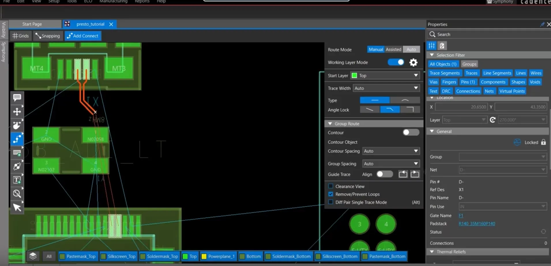
Improving Signal Integrity
- Adjust Trace Routing: If possible, redesign the PCB to keep high-speed traces (e.g., for Ethernet signals at 1 Gbps) away from noisy areas. Use ground planes to reduce interference.
- Add Termination Resistors: For impedance matching, add resistors (typically 50 ohms) at the end of high-speed lines if your design lacks them.
Stabilizing Power Supply
- Replace Faulty Components: If a voltage regulator or capacitor is malfunctioning, replace it with one of the same specifications (e.g., a 5V regulator with a 1A output capacity).
- Add Decoupling Capacitors: Place capacitors near power pins of ICs to filter noise. A common value is 0.1μF for high-frequency noise suppression.
Preventing Future Issues in DIY PCB Design
Troubleshooting is essential, but prevention is even better. Here are some tips to avoid common problems in your next router or switch PCB project.
- Double-Check Schematics: Before manufacturing, verify your schematic for errors in connections or component values.
- Use Design Rules: Set proper clearance (at least 0.2mm between traces) and trace width (0.3mm for power traces) in your design software to prevent shorts and signal issues.
- Test in Simulation: Use simulation tools to test signal integrity and power distribution before fabricating the board.
Tools You Need for Effective PCB Debugging
Having the right tools can make troubleshooting much easier. Here’s a list of essentials for debugging your DIY PCB:
- Multimeter: For testing continuity, voltage, and current. A basic model costs around $20 and is invaluable for detecting shorts and open circuits.
- Oscilloscope: For analyzing signal integrity, especially in high-speed designs. Entry-level models start at $200.
- Soldering Kit: Includes a soldering iron, desoldering tools, and flux for fixing solder-related issues.
- Magnifying Glass or Microscope: For inspecting small components and solder joints.
When to Seek Professional Help
While many issues can be resolved at home, some problems might require advanced expertise or equipment. If you've exhausted all troubleshooting steps and your board still doesn't work, consider consulting with a professional engineer or using advanced diagnostic tools. This is especially true for complex multilayer boards or when dealing with high-speed signals above 2.5 Gbps, where precise impedance control is critical.
Conclusion
Troubleshooting your DIY router or switch PCB can be a daunting task, but with the right approach, you can identify and fix common issues like shorts, open circuits, and signal integrity problems. By following a systematic debugging process—starting with visual inspection, testing with a multimeter, and verifying functionality—you can resolve most problems and ensure your board operates as intended. Additionally, adopting best practices in design and assembly will help prevent future issues, saving you time and effort.
With the solutions and tips provided in this guide, you're well-equipped to tackle router switch issues and refine your skills in debugging PCBs. Keep experimenting, stay patient, and enjoy the process of bringing your DIY projects to life!


