ALLPCB


In the fast-evolving world of electronics, managing heat in printed circuit boards (PCBs) is a critical challenge. As devices become smaller and more powerful, heat dissipation in PCBs can impact performance and reliability. So, how can engineers tackle this issue effectively? One innovative solution lies in using embedded components for thermal management. This approach, combined with advanced PCB cooling techniques, offers a breakthrough in maintaining optimal temperatures and extending the lifespan of electronic systems.
In this blog post, we’ll dive deep into the concept of embedded components thermal management, explore various PCB cooling techniques, and discuss how thermal vias for embedded components play a vital role in heat dissipation. We’ll also cover the importance of PCB thermal analysis to ensure your designs stay cool under pressure. Let’s explore how these strategies can revolutionize your PCB designs.
Why Thermal Management Matters in PCB Design
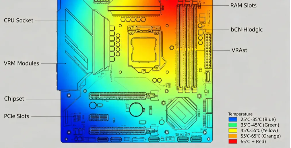
Heat is an inevitable byproduct of electronic components in operation. When not managed properly, excessive heat can lead to reduced performance, component failure, or even complete system breakdowns. With the trend toward miniaturization, components are packed closer together, leaving little room for heat to escape. This makes efficient thermal management more important than ever.
Effective heat dissipation in PCBs ensures that components operate within safe temperature ranges, typically between 0°C to 85°C for most commercial-grade electronics. Without proper cooling, temperatures can exceed these limits, causing thermal stress that degrades solder joints or damages sensitive parts. By integrating advanced cooling methods like embedded components, designers can address these challenges head-on.
What Are Embedded Components in Thermal Management?
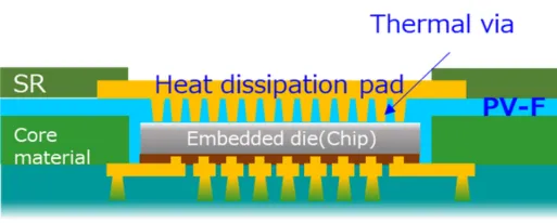
Embedded components refer to electronic parts that are integrated directly into the layers of a PCB rather than being mounted on the surface. This technique is often used for space-saving purposes, but it also offers significant benefits for thermal management. By placing components like resistors, capacitors, or even small heat sinks within the PCB substrate, heat can be distributed more evenly across the board.
Embedded components thermal management works by reducing the thermal resistance between heat-generating elements and the surrounding materials. For instance, embedding a power resistor inside a PCB layer near a conductive plane allows heat to spread out instead of concentrating in one spot. This method can lower peak temperatures by up to 20-30% compared to surface-mounted designs, based on industry studies of high-density boards.
This approach is particularly useful in applications like automotive electronics or high-power LED systems, where heat loads are significant. By strategically positioning embedded components, engineers can create a more thermally balanced design that prevents overheating.
Key PCB Cooling Techniques for Enhanced Heat Dissipation
Beyond embedded components, several PCB cooling techniques can be employed to improve heat dissipation. Combining these methods with embedded designs can yield even better results. Let’s explore some of the most effective strategies.
1. Use of Thermal Vias for Embedded Components
Thermal vias are small holes filled or plated with conductive material, typically copper, that transfer heat from one layer of the PCB to another. When used with embedded components, thermal vias for embedded components act as conduits to move heat away from critical areas to a heat sink or external layer for dissipation.
For example, placing an array of thermal vias beneath an embedded power component can reduce its operating temperature by channeling heat to a ground plane. Studies suggest that a well-designed via array can lower junction temperatures by 10-15°C in high-power applications. The key is to optimize via size and spacing—common via diameters range from 0.3mm to 0.5mm, with a pitch of 1.0mm often providing a good balance between thermal performance and structural integrity.
2. Copper Planes and Traces for Heat Spreading
Copper is an excellent conductor of heat, with a thermal conductivity of approximately 400 W/m·K. By incorporating large copper planes or thick traces in PCB designs, heat can be spread across a wider area, reducing localized hot spots. This technique works well with embedded components, as the proximity to copper layers enhances heat transfer.
In practice, designers often use inner copper layers as dedicated heat-spreading planes. For instance, a 2 oz/ft2 copper layer can handle significant thermal loads in power electronics, dissipating heat more effectively than a standard 1 oz/ft2 layer. This method is cost-effective and can be easily integrated into most PCB layouts.
3. Advanced Materials for Better Thermal Conductivity
The choice of PCB substrate material plays a huge role in thermal management. Standard FR-4 materials have a thermal conductivity of about 0.3 W/m·K, which is insufficient for high-heat applications. Switching to advanced materials like metal-core PCBs (MCPCBs) or ceramic-based substrates can dramatically improve heat dissipation in PCBs.
Metal-core boards, often made with an aluminum base, offer thermal conductivities up to 1-2 W/m·K, making them ideal for designs with embedded components. These materials not only conduct heat better but also provide structural support, ensuring reliability in harsh environments like industrial or aerospace systems.
The Role of PCB Thermal Analysis in Design Optimization
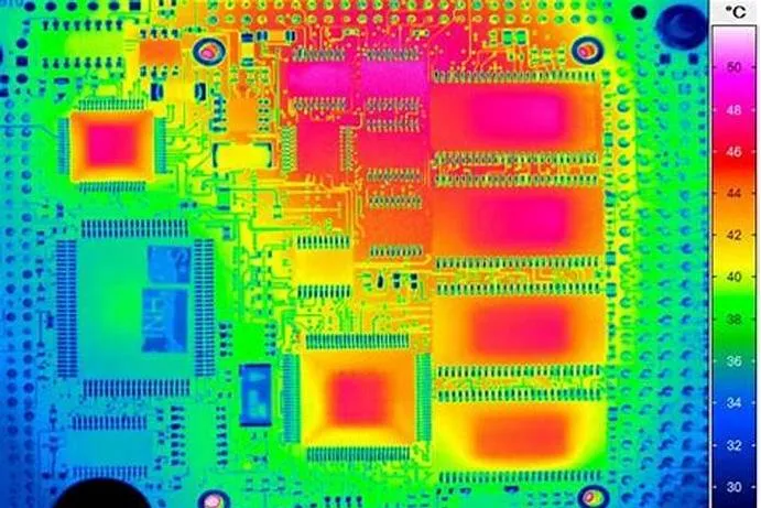
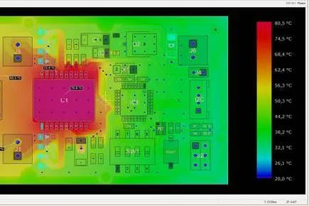
Designing for thermal management is only half the battle—validating your approach through PCB thermal analysis is equally important. Thermal analysis involves simulating the heat flow and temperature distribution within a PCB to identify potential issues before manufacturing.
Using software tools, engineers can model how heat moves through embedded components, thermal vias, and copper planes under various operating conditions. For example, a simulation might reveal that a specific embedded component reaches 90°C during peak load, exceeding its safe limit of 85°C. Armed with this data, designers can adjust via placement or add a heat sink to bring temperatures down to acceptable levels.
Thermal analysis also helps optimize material selection and layout. By running simulations with different substrate materials or copper thicknesses, you can determine the most cost-effective combination for your design. This process can save significant time and resources by preventing costly redesigns after prototyping.
Benefits of Embedded Components for Thermal Management
Integrating embedded components into your PCB design offers several advantages beyond just heat dissipation. Let’s break down some of the key benefits:
- Space Efficiency: Embedding components frees up surface area for other parts or reduces the overall board size, which is critical in compact devices like wearables or IoT modules.
- Improved Reliability: By minimizing thermal stress, embedded designs reduce the risk of solder joint failures or component degradation, extending the product’s lifespan.
- Better Signal Integrity: Embedding components closer to their connection points can reduce parasitic inductance and capacitance, improving high-speed signal performance. Typical reductions in inductance can be in the range of 10-20 nH compared to surface-mounted setups.
- Enhanced Heat Distribution: As mentioned earlier, embedding allows heat to spread more evenly, preventing localized overheating that could damage nearby components.
Challenges and Considerations in Using Embedded Components
While the benefits are clear, embedded components thermal management comes with its own set of challenges. Understanding these hurdles can help you make informed decisions during the design phase.
First, manufacturing complexity increases with embedded designs. Embedding components requires precise layer alignment and specialized fabrication processes, which can raise production costs. Additionally, once embedded, components are difficult to access for repairs or replacements, making thorough testing and simulation essential before finalizing the design.
Another consideration is the thermal expansion mismatch between embedded components and the surrounding PCB material. Different coefficients of thermal expansion (CTE) can lead to mechanical stress during temperature fluctuations. For instance, a ceramic capacitor with a CTE of 6-8 ppm/°C may not align well with an FR-4 substrate at 14-18 ppm/°C, potentially causing cracks over time. Selecting materials with compatible CTE values or adding stress-relief features can mitigate this risk.
Practical Tips for Implementing Embedded Components in PCB Cooling
To help you get started with embedded components for thermal management, here are some actionable tips that can be applied to your next project:
- Plan Early: Incorporate thermal management into the initial design phase. Identify heat-generating components and decide whether embedding them will provide the best cooling solution.
- Optimize Via Arrays: Use thermal vias strategically around embedded components to create efficient heat paths. Aim for a via density that balances thermal performance with board strength.
- Leverage Simulation Tools: Invest in PCB thermal analysis software to predict temperature profiles and refine your design. Many tools offer user-friendly interfaces to model heat flow in minutes.
- Choose the Right Materials: Evaluate substrate options based on thermal conductivity and cost. For high-heat designs, consider metal-core or high-Tg materials to enhance heat dissipation in PCBs.
- Test Thoroughly: Build prototypes and conduct real-world thermal testing to validate simulation results. Use infrared cameras or thermocouples to measure temperatures at critical points.
Future Trends in PCB Thermal Management
As technology continues to advance, so do the methods for managing heat in PCBs. One emerging trend is the use of active cooling solutions, such as micro-fans or liquid cooling channels integrated into PCB designs. While these are still in the experimental stage for most applications, they hold promise for ultra-high-power systems.
Another area of innovation is the development of new materials with superior thermal properties. Graphene-based substrates, for instance, offer thermal conductivities exceeding 1000 W/m·K in some configurations, far surpassing traditional materials. Although cost remains a barrier, ongoing research may soon make these options viable for mainstream use.
Embedded components are also evolving, with manufacturers exploring ways to integrate more complex parts like microcontrollers or power modules directly into PCB layers. This could further enhance thermal management by reducing surface heat sources while improving overall design efficiency.
Conclusion: Revolutionizing PCB Design with Embedded Components
Thermal management is a cornerstone of reliable PCB design, especially as electronic devices push the boundaries of power and compactness. By leveraging embedded components thermal management, engineers can achieve efficient heat dissipation in PCBs, ensuring optimal performance and longevity. Techniques like thermal vias for embedded components, copper planes, and advanced materials provide powerful tools to combat overheating, while PCB thermal analysis helps validate and refine these solutions.