ALLPCB


Choosing the right materials for your double-layer PCB is crucial for ensuring performance, reliability, and cost-effectiveness in your electronic projects. Whether you're designing for a simple consumer device or a complex industrial application, the materials you select—especially the substrate and dielectric—can impact everything from signal integrity to thermal management. In this guide, we'll dive deep into PCB material selection, focusing on popular options like FR-4 PCB materials, various PCB substrate materials, and the importance of PCB dielectric properties. Let's explore how to make informed decisions for your double-layer PCB designs.
Why PCB Material Selection Matters for Double-Layer Boards
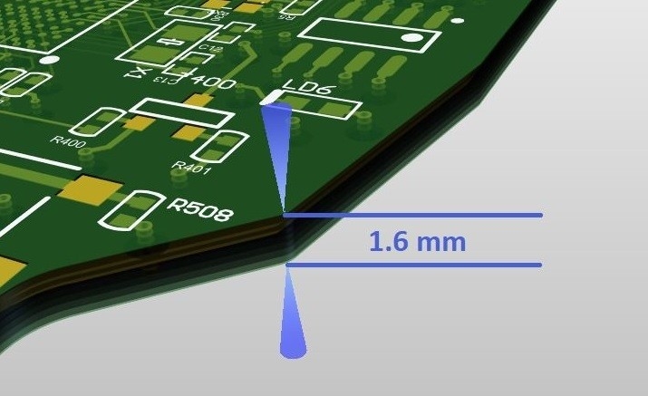
Double-layer PCBs, which consist of two layers of conductive copper separated by an insulating substrate, are widely used due to their balance of complexity and affordability. The materials you choose directly affect the board's electrical performance, mechanical strength, and ability to withstand environmental factors like heat and humidity. Poor material choices can lead to issues like signal loss, overheating, or even board failure. By understanding key material properties, you can optimize your design for both functionality and durability.
Understanding PCB Substrate Materials: The Foundation of Your Board
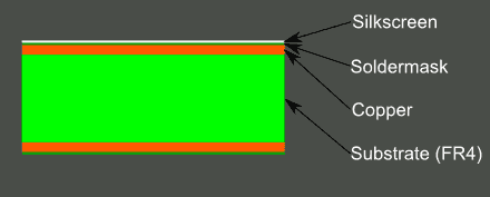
The substrate is the core material that provides structural support and insulation between the conductive layers of a PCB. For double-layer boards, the substrate must balance electrical insulation, thermal stability, and cost. Here are some common PCB substrate materials to consider:
1. FR-4: The Industry Standard
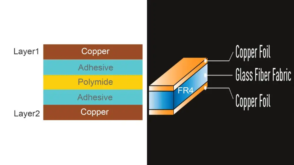
FR-4 PCB material is the most widely used substrate for double-layer boards. Made from woven fiberglass cloth and epoxy resin, FR-4 offers a good mix of affordability, durability, and performance. Its key characteristics include:
- Dielectric Constant (Dk): Typically around 4.5 at 1 MHz, making it suitable for standard applications with moderate signal speeds.
- Thermal Conductivity: About 0.3 W/m·K, which is adequate for low to medium power designs but may require additional heat management for high-power applications.
- Cost: Low compared to high-frequency or specialty materials, making it ideal for most consumer and industrial projects.
FR-4 is versatile and works well for double-layer PCBs in applications like home appliances, automotive electronics, and basic IoT devices. However, it may not be suitable for high-frequency designs (above 1 GHz) due to signal loss caused by its relatively high dielectric constant.
2. High-Tg FR-4: For Enhanced Thermal Stability
For designs that operate in higher temperature environments, High-Tg (glass transition temperature) FR-4 is a better choice. Standard FR-4 has a Tg of about 130°C, while High-Tg variants range from 150°C to 170°C. This makes them more resistant to deformation under heat, which is critical for double-layer PCBs in automotive or industrial settings.
3. Alternative Substrates for Specialized Needs
While FR-4 dominates the market, other PCB substrate materials may be necessary for specific double-layer PCB applications:
- Polyimide: Offers excellent thermal stability (Tg above 250°C) and flexibility, often used in flexible or high-temperature double-layer PCBs. However, it comes at a higher cost.
- PTFE-Based Materials: Known for low dielectric constants (around 2.1 to 3.0), these are ideal for high-frequency applications but are significantly more expensive than FR-4.
- Ceramic Substrates: Used in extreme environments due to their superior thermal conductivity (up to 30 W/m·K) and stability, though they are costly and less common in standard double-layer designs.
PCB Dielectric Properties: Why They Matter
The dielectric properties of a PCB material determine how it interacts with electric fields, which is critical for signal integrity in double-layer boards. The two main dielectric properties to consider during PCB material selection are the dielectric constant (Dk) and the dissipation factor (Df).
1. Dielectric Constant (Dk)
The dielectric constant measures how much a material can store electrical energy in an electric field. A lower Dk means faster signal propagation, which is essential for high-speed designs. For example:
- FR-4 has a Dk of approximately 4.5, suitable for frequencies up to 1 GHz.
- High-frequency materials like PTFE have a Dk of 2.1 to 3.0, allowing signal speeds to approach 70% of the speed of light in a vacuum, compared to about 50% in FR-4.
For double-layer PCBs in standard applications, FR-4's Dk is usually sufficient. However, if your design involves high-speed data transmission (e.g., USB 3.0 or HDMI interfaces), consider a material with a lower Dk to minimize signal delay and impedance mismatch.
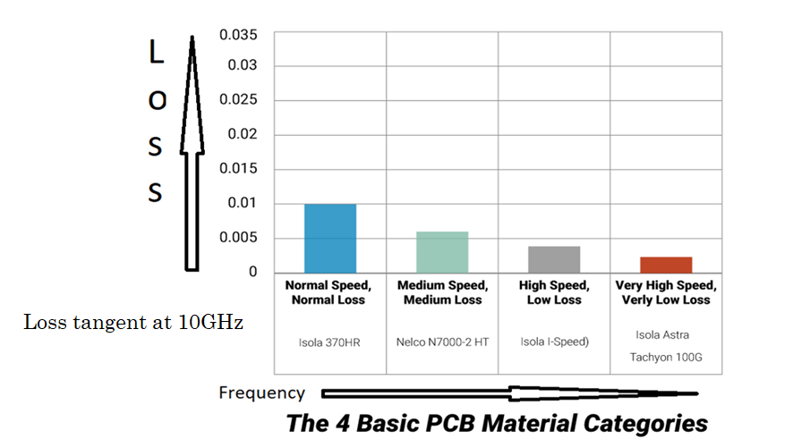
2. Dissipation Factor (Df)
The dissipation factor indicates how much energy is lost as heat when a signal passes through the material. A lower Df means less signal loss. FR-4 typically has a Df of 0.02, which is acceptable for most applications but can cause noticeable signal degradation at frequencies above 1 GHz. In contrast, high-frequency materials often have a Df below 0.005, ensuring better performance in demanding designs.
Understanding these PCB dielectric properties helps you match the material to your project's electrical requirements, ensuring reliable performance for your double-layer PCB.
Factors to Consider in PCB Material Selection for Double-Layer Boards
Beyond substrate type and dielectric properties, several other factors play a role in PCB material selection. Let's break them down to help you make an informed choice.
1. Electrical Performance Requirements
Consider the frequency and speed of the signals your PCB will handle. For low to medium frequencies (below 1 GHz), FR-4 is usually fine. For high-speed or RF applications, you might need materials with lower Dk and Df values to maintain signal integrity. For instance, a double-layer PCB for a 5G device may require a PTFE-based substrate to handle frequencies up to 6 GHz without significant signal loss.
2. Thermal Management Needs
Double-layer PCBs in high-power applications generate heat, which can degrade performance if not managed properly. FR-4 has limited thermal conductivity (0.3 W/m·K), so for designs with high heat dissipation, consider adding thermal vias or opting for a substrate with better heat transfer capabilities, like ceramic or metal-core materials. This is especially important in LED lighting or power supply designs.
3. Environmental Conditions
Think about where your PCB will be used. Will it be exposed to moisture, extreme temperatures, or chemicals? FR-4 offers decent resistance to humidity and moderate temperatures, but for harsh environments, polyimide or ceramic substrates provide better reliability. For example, a double-layer PCB in an outdoor sensor might benefit from polyimide’s resistance to temperature swings.
4. Cost Constraints
Budget is always a key consideration. FR-4 is the most cost-effective option for double-layer PCBs, often costing 50-70% less than specialty materials like PTFE or ceramic. If your design doesn’t require high-frequency or extreme thermal performance, sticking with FR-4 can save significant costs without sacrificing quality.
Step-by-Step Guide to Selecting Materials for Double-Layer PCBs
Now that you understand the key materials and factors, follow this practical approach to choose the right materials for your double-layer PCB:
- Define Your Application: Identify the purpose of your PCB. Is it for a consumer gadget, automotive system, or high-speed communication device? This sets the baseline for material requirements.
- Assess Electrical Needs: Determine the frequency and signal speed requirements. Use FR-4 for standard designs or explore low-Dk materials for high-frequency needs.
- Evaluate Thermal and Environmental Demands: Check if your PCB will face high heat or harsh conditions. Opt for High-Tg FR-4 or alternative substrates if standard FR-4 falls short.
- Set a Budget: Balance performance with cost. If specialty materials aren’t necessary, FR-4 offers excellent value for most double-layer PCB projects.
- Test and Validate: Once you’ve selected a material, prototype your design to confirm it meets performance expectations. Adjust if needed based on testing data.
Common Challenges and Solutions in Double-Layer PCB Material Selection
Even with careful planning, challenges can arise during PCB material selection. Here are a few common issues and how to address them:
- Signal Integrity Issues: If you notice signal loss or crosstalk in high-speed designs, switch to a material with a lower dielectric constant and dissipation factor. Adding ground planes in your double-layer design can also help.
- Thermal Overload: For heat-related problems, integrate thermal vias or heat sinks into your PCB layout. If that’s not enough, consider a substrate with higher thermal conductivity.
- Cost Overruns: If specialty materials push your budget too high, revisit your design requirements. Often, optimizing the layout or using standard materials with minor adjustments can achieve similar results at a lower cost.
Conclusion: Building Better Double-Layer PCBs with the Right Materials
Selecting the right materials for your double-layer PCB is a critical step that impacts the success of your electronic project. By focusing on PCB material selection, understanding the benefits of FR-4 PCB materials, exploring various PCB substrate materials, and prioritizing PCB dielectric properties, you can create a board that meets your performance and budget needs. Whether you stick with the reliable and cost-effective FR-4 or opt for a specialty substrate for high-frequency or high-temperature applications, informed decisions lead to better designs.
At ALLPCB, we’re committed to supporting your journey with resources and expertise to bring your designs to life. Use this guide as a foundation to choose the best materials for your double-layer PCB and achieve outstanding results in your next project.