 ALLPCB


Looking to reduce the cost of manufacturing rigid flex PCBs without compromising on quality? One of the most effective alternatives is to explore semi-flex PCBs, which offer a balance between flexibility and cost savings. By optimizing design, choosing the right materials, and streamlining manufacturing steps, you can significantly lower expenses. In this comprehensive guide, we’ll dive deep into strategies for cutting rigid flex PCB cost, explore semi-flex PCB manufacturing cost as a viable option, and discuss alternative technology cost, manufacturing steps cost, and design cost alternatives to help you save money while maintaining performance.
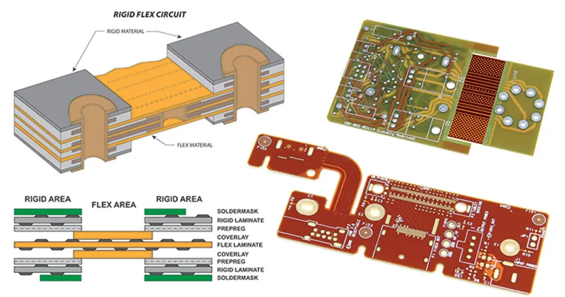
What Are Rigid Flex PCBs and Why Are They Expensive?
Rigid flex PCBs combine the benefits of rigid and flexible circuits into a single board, making them ideal for compact, high-performance applications like aerospace, medical devices, and consumer electronics. These boards consist of rigid sections for mounting components and flexible sections for bending or folding, reducing the need for connectors and cables. However, their unique construction drives up costs due to several factors:
- Complex Materials: Rigid flex PCBs use specialized materials like polyimide for flexible layers, which are more expensive than standard FR-4 used in rigid boards.
- Manufacturing Complexity: The process involves multiple steps, such as laminating rigid and flexible layers, precise drilling, and specialized plating, which increase labor and equipment costs.
- Low Yield Rates: Due to the intricate design and tight tolerances, manufacturing defects are more common, leading to higher scrap rates and costs.
- Layer Count: More layers mean higher material and processing expenses, often necessary for complex designs.
Understanding these cost drivers is the first step to identifying ways to reduce expenses. Let’s explore how to tackle rigid flex PCB cost with practical solutions and alternatives like semi-flex PCBs.
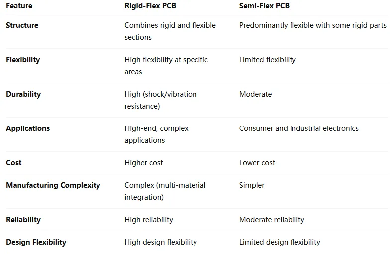
Semi-Flex PCBs: A Cost-Effective Alternative to Rigid Flex
If your project doesn’t require extreme flexibility, semi-flex PCBs can be a game-changer for reducing semi-flex PCB manufacturing cost compared to rigid flex. Semi-flex PCBs are made from standard FR-4 material that is thinned in specific areas to allow limited bending. They are not as flexible as true rigid flex boards but are sufficient for applications needing a one-time bend or slight flexibility during installation.
Key Benefits of Semi-Flex PCBs for Cost Savings
- Lower Material Costs: Semi-flex PCBs use standard FR-4 instead of costly polyimide, slashing material expenses by up to 30-40% in some cases.
- Simplified Manufacturing: The process involves fewer specialized steps, reducing labor and equipment costs. For instance, semi-flex boards don’t require complex lamination of different material types.
- Higher Yield Rates: With simpler construction, there’s less risk of defects, meaning fewer boards are scrapped during production.
- Compatibility with Existing Designs: Semi-flex PCBs can often replace rigid flex in applications with minimal bending requirements, saving on redesign costs.
By switching to semi-flex where full flexibility isn’t critical, you can achieve significant savings on alternative technology cost without sacrificing functionality.
Strategies to Reduce Rigid Flex PCB Manufacturing Costs
While semi-flex PCBs are a great alternative, some projects still require the full capabilities of rigid flex. Here are actionable strategies to lower rigid flex PCB cost during design and manufacturing.
1. Optimize Layer Count
The number of layers in a rigid flex PCB directly impacts cost. Each additional layer increases material usage, processing time, and the risk of defects. For example, a 6-layer rigid flex board can cost 20-30% more than a 4-layer board due to added complexity. To minimize layers:
- Review your design to consolidate traces and components into fewer layers where possible.
- Use high-density interconnect (HDI) techniques to pack more functionality into a smaller space, potentially reducing the need for extra layers.
2. Choose Cost-Effective Materials
Material selection plays a huge role in manufacturing steps cost. While polyimide is standard for flexible sections, not all applications need high-end variants. Work with your manufacturer to identify lower-cost materials with similar performance. For instance, using a less expensive adhesive system for bonding layers can save up to 10-15% on material costs without affecting reliability for many applications.
3. Simplify Design for Manufacturability
Complex designs with tight tolerances, numerous vias, and intricate bend areas increase manufacturing difficulty and cost. Simplify your design by:
- Reducing the number of bend zones, as each bend area requires precise alignment and additional processing.
- Minimizing microvias and blind vias, which are costly to drill and plate. For example, replacing microvias with through-hole vias can cut drilling costs by 5-10%.
- Standardizing component sizes and placements to avoid custom tooling or setups.
These adjustments can lower design cost alternatives and improve yield rates, saving money in the long run.
4. Increase Order Volume for Economies of Scale
Manufacturing costs per unit drop significantly with larger production runs. For instance, producing 100 rigid flex PCBs might cost $50 per unit, while producing 1,000 could reduce the cost to $30 per unit due to setup costs being spread across more boards. If possible, plan for larger batches to take advantage of economies of scale.
Breaking Down Manufacturing Steps Cost
Understanding the manufacturing steps cost for rigid flex PCBs helps identify where savings are possible. Here’s a breakdown of key steps and tips to reduce expenses at each stage:
1. Material Preparation and Lamination
This step involves cutting and bonding rigid and flexible materials. Costs can be high due to specialized adhesives and precise alignment. To save:
- Use standard material thicknesses to avoid custom orders, which can add 10-20% to costs.
- Minimize waste by optimizing panel layouts during design.
2. Drilling and Routing
Drilling vias and routing flexible sections are labor-intensive. Microvias, often used in HDI designs, can cost 2-3 times more than standard vias due to precision requirements. Cost-saving tips include:
- Reduce the number of vias by optimizing trace routing.
- Use larger via sizes where signal integrity allows, as they’re cheaper to drill.
3. Plating and Etching
Plating ensures conductivity across layers, but it’s expensive for rigid flex due to the need for uniform coverage on flexible sections. Etching defines the circuit patterns but can lead to material waste. To cut costs:
- Stick to standard copper weights (e.g., 1 oz/ft2) instead of heavier options unless necessary for current capacity. For example, moving from 2 oz to 1 oz copper can save 5-8% on plating costs.
- Ensure design files are error-free to avoid rework during etching.
4. Testing and Quality Control
Rigid flex PCBs require rigorous testing (e.g., electrical continuity, bend testing) to ensure reliability, which adds to costs. Save by:
- Designing for testability with accessible test points, reducing testing time.
- Partnering with a manufacturer that offers automated testing to lower labor costs.
By addressing costs at each stage, you can achieve substantial savings on overall manufacturing steps cost.
Design Cost Alternatives for Rigid Flex PCBs
Design is another area where costs can spiral if not managed carefully. Here are some design cost alternatives to keep expenses in check:
1. Use Open-Source Design Tools
Instead of investing in expensive proprietary software, leverage free or open-source PCB design tools that offer robust features for creating rigid flex layouts. These tools can save hundreds or thousands of dollars in licensing fees while still providing the functionality needed for complex designs.
2. Collaborate with Manufacturers Early
Engage with your manufacturing partner during the design phase. Many offer free design reviews to catch potential issues that could increase costs, such as non-standard materials or overly tight tolerances. Early collaboration can save 10-15% on redesign costs by avoiding mistakes before production begins.
3. Reuse Proven Designs
If your project allows, reuse existing rigid flex designs or modules that have been tested and validated. This approach minimizes design time and reduces the risk of errors, cutting down on both time and cost.
Alternative Technology Cost: Beyond Semi-Flex
Besides semi-flex PCBs, other technologies can serve as alternatives to rigid flex for specific applications, further reducing alternative technology cost. Consider these options:
1. Rigid PCBs with Flexible Cables
For designs that don’t require integrated flexibility, use standard rigid PCBs connected by flexible cables or ribbon connectors. This setup is far cheaper, as rigid PCBs cost 50-70% less than rigid flex, and cables are inexpensive. However, this increases assembly time and may not suit compact designs.
2. Modular Designs
Break your design into smaller, separate rigid boards connected via connectors or cables. While this doesn’t offer the same space savings as rigid flex, it reduces manufacturing complexity and costs by avoiding flexible layers entirely.
3. Hybrid Approaches
In some cases, combining rigid, semi-flex, and minimal flexible sections can balance cost and performance. For example, using semi-flex for slight bends and rigid for component-heavy areas can cut costs by 20-30% compared to a full rigid flex design.
Final Thoughts on Reducing Rigid Flex PCB Costs
Reducing the rigid flex PCB cost doesn’t mean cutting corners on quality. By exploring alternatives like semi-flex PCBs, optimizing designs, selecting cost-effective materials, and streamlining manufacturing processes, you can achieve significant savings. Whether you’re tackling semi-flex PCB manufacturing cost, evaluating alternative technology cost, or seeking design cost alternatives, the strategies outlined here provide a roadmap to cost-effective solutions.
Start by assessing your project’s specific needs. Does it require full rigid flex capabilities, or can a semi-flex or hybrid approach work? Collaborate with your manufacturing partner to refine designs and choose the right materials. With careful planning, you can lower manufacturing steps cost and deliver high-quality PCBs within budget.
Suggested Image Placement: Add a final image here of a finished rigid flex PCB in a real-world application, such as a wearable device or aerospace component. ALT Text: " "
"


