 ALLPCB


Designing a high-current PCB for a power tool charger is a complex task that requires careful planning to ensure safety, efficiency, and durability. Power tools demand robust battery chargers capable of handling high currents while maintaining thermal stability and long-term reliability. In this blog post, we’ll dive deep into the key considerations for creating a high-current battery charger PCB tailored for power tools, focusing on thermal management, the use of heavy copper PCB, and building a robust PCB design.
Whether you're an engineer working on power tool charger designs or a manufacturer looking to optimize your PCB for high-current applications, this guide offers practical insights and actionable tips to help you succeed. Let’s explore the critical factors that go into designing a reliable and efficient PCB for power tool battery chargers.
Why High-Current PCB Design Matters for Power Tools
Power tools like drills, saws, and grinders rely on high-capacity batteries to deliver the performance users expect. These batteries, often lithium-ion, require chargers that can supply high currents—sometimes exceeding 10A or more—to recharge quickly and efficiently. A poorly designed PCB in a power tool charger can lead to overheating, voltage drops, or even component failure, which compromises both safety and performance.
A high-current PCB must handle significant electrical loads without degrading over time. This means paying close attention to trace width, material selection, and thermal dissipation. Additionally, the PCB must be robust enough to withstand the mechanical stresses and vibrations often encountered in power tool environments. Let’s break down the essential considerations for designing such a PCB.
1. Understanding High-Current Requirements for Power Tool Chargers
Power tool chargers often need to deliver currents ranging from 5A to 20A, depending on the battery capacity and charging speed. For instance, a 4Ah battery with a 2C charging rate requires a charger capable of supplying 8A continuously. High currents generate heat and stress on the PCB, so the design must account for these factors from the start.
The first step is to calculate the current-carrying capacity needed for the traces. According to standard PCB design guidelines, a trace width of 100 mils (2.54 mm) on a 1 oz copper layer can handle approximately 2.5A of current. For a 10A load, you’d need a trace width of at least 400 mils (10.16 mm) or opt for a heavier copper layer, which we’ll discuss later. Failing to provide adequate trace width can result in excessive resistance, leading to voltage drops and heat buildup.
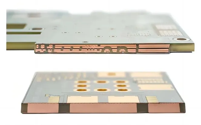
2. Leveraging Heavy Copper PCB for High-Current Applications
One of the most effective ways to manage high currents in a power tool charger is by using a heavy copper PCB. Standard PCBs typically use 1 oz or 2 oz copper layers (35 μm or 70 μm thick), but heavy copper PCBs can feature copper weights of 3 oz (105 μm) or more. This added thickness significantly increases the current-carrying capacity and reduces resistance, minimizing heat generation.
For example, a 3 oz copper layer can carry roughly three times the current of a 1 oz layer for the same trace width. This means a 100-mil trace on a 3 oz copper PCB can handle around 7.5A, reducing the need for excessively wide traces and saving valuable board space. Heavy copper also improves the PCB’s mechanical strength, making it more robust against physical stress—a critical factor for power tools often used in rugged conditions.
However, heavy copper PCBs come with higher manufacturing costs and may require specialized fabrication processes. It’s essential to balance performance needs with budget constraints when deciding on copper weight. For most high-current power tool chargers, a 3 oz or 4 oz copper layer offers a good compromise between capability and cost.
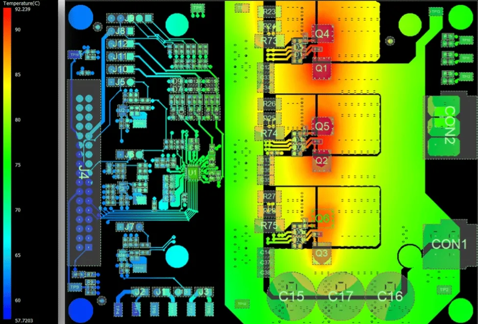
3. Prioritizing Thermal Management in High-Current PCB Design
Thermal management is a top concern when designing a high-current PCB for power tool chargers. High currents generate significant heat through resistive losses in traces and components like MOSFETs, diodes, and inductors. If this heat isn’t dissipated effectively, it can lead to component failure, reduced charging efficiency, or even safety hazards like thermal runaway in lithium-ion batteries.
Here are several strategies to enhance thermal management in your PCB design:
- Use Thermal Vias: Place thermal vias under heat-generating components to transfer heat from the top layer to a ground plane or heat sink on the bottom layer. For instance, a grid of 0.3 mm vias spaced 1 mm apart can significantly improve heat dissipation.
- Incorporate Heat Sinks: Attach heat sinks to high-power components like voltage regulators or power transistors to draw heat away from the PCB. Ensure proper mounting and thermal paste for optimal performance.
- Optimize Component Placement: Position heat-generating components away from sensitive parts like microcontrollers. Spread out high-current traces to avoid localized hot spots.
- Choose High-Thermal-Conductivity Materials: Select PCB substrates with better thermal conductivity, such as metal-core PCBs, for extreme high-current designs. These materials can dissipate heat more effectively than standard FR-4.
By implementing these techniques, you can keep operating temperatures within safe limits, typically below 85°C for most components, ensuring the longevity of your power tool charger.
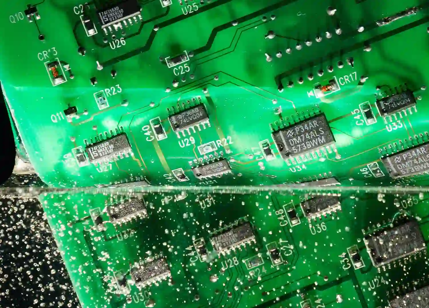
4. Building a Robust PCB for Power Tool Environments
Power tools are often used in harsh environments where dust, moisture, and vibrations are common. A robust PCB design is crucial to ensure the charger withstands these conditions without failing. Here are key factors to consider for durability:
- Thicker PCB Material: Use a thicker PCB substrate, such as 2.0 mm or 2.4 mm, instead of the standard 1.6 mm. This added thickness provides better mechanical strength against vibrations and impacts.
- Conformal Coating: Apply a conformal coating to protect the PCB from moisture, dust, and chemical exposure. Silicone or acrylic coatings are commonly used for power tool electronics.
- Secure Component Mounting: Use through-hole components or additional adhesives for large components like capacitors and inductors to prevent them from loosening due to vibration.
- Strain Relief for Connectors: Design strain relief into cable connections and mounting points to prevent stress on solder joints, which could crack under repeated mechanical stress.
A robust PCB not only extends the lifespan of the power tool charger but also enhances user safety by reducing the risk of electrical failures in demanding conditions.
5. Ensuring Safety and Compliance in High-Current Designs
Safety is non-negotiable when designing a high-current PCB for power tool chargers. High currents and voltages pose risks of short circuits, overheating, and electrical shocks if not managed properly. Here are critical safety considerations:
- Proper Insulation and Clearance: Maintain adequate spacing between high-voltage traces to prevent arcing. For example, at 48V, a minimum clearance of 0.6 mm is recommended under standard safety guidelines.
- Overcurrent Protection: Integrate fuses or circuit breakers to protect against overcurrent conditions. A 15A fast-blow fuse can prevent damage if a short circuit occurs during charging.
- Ground Planes: Use large ground planes to reduce electromagnetic interference (EMI) and provide a low-impedance path for fault currents, enhancing safety.
- Compliance with Standards: Ensure your design meets industry standards like IEC 60950 for information technology equipment or UL 2054 for battery safety. Compliance not only ensures safety but also builds trust with end-users.
By prioritizing safety in your design, you protect both the equipment and the users, which is especially important for power tools used in professional settings.
6. Optimizing Layout for Efficiency and Performance
The layout of a high-current PCB directly impacts its efficiency and performance in a power tool charger. A well-thought-out layout minimizes parasitic inductance, reduces EMI, and ensures stable power delivery. Follow these tips for an optimized layout:
- Minimize Loop Areas: Keep the current loops for high-power switching circuits as small as possible to reduce inductance. For example, place decoupling capacitors close to power ICs to stabilize voltage.
- Separate Analog and Digital Grounds: Use separate ground planes for analog and digital signals to prevent noise interference, which can disrupt battery charging control circuits.
- Route High-Current Traces First: Prioritize routing high-current paths to ensure they have the shortest and widest paths possible, reducing resistance and heat.
- Avoid Right-Angle Bends: Use smooth curves or 45-degree angles for high-current traces to prevent current crowding, which can lead to localized heating.
An efficient layout not only improves the charger’s performance but also simplifies debugging and manufacturing, saving time and resources in the long run.
Conclusion: Building Reliable Power Tool Chargers with High-Current PCBs
Designing a high-current PCB for power tool chargers is a challenging but rewarding endeavor. By focusing on critical aspects like heavy copper PCB selection, thermal management, and robust PCB construction, you can create a charger that meets the demanding needs of power tools while ensuring safety and efficiency. From calculating trace widths to integrating thermal vias and ensuring compliance with safety standards, every detail matters in achieving a reliable design.
At ALLPCB, we understand the unique challenges of high-current PCB design and are committed to supporting engineers with the tools and resources needed to bring their ideas to life. Whether you’re working on a power tool charger or another high-power application, thoughtful design and attention to detail are the keys to success. Let’s build the future of power electronics together with innovative and durable solutions.


