ALLPCB


Are you looking to take control of your home with custom smart home automation solutions? Building your own PCBs (Printed Circuit Boards) for smart home automation is a rewarding way to create tailored systems that control lighting, security, temperature, and more. In this comprehensive guide, we’ll walk you through the process of designing and building custom PCBs for your DIY home automation projects. From choosing the right design software to troubleshooting and securing your boards, we’ve got you covered with practical tips and detailed insights.
Whether you’re a hobbyist or an experienced engineer, this blog will dive deep into DIY home automation PCB projects, home automation PCB design software, open source home automation PCB schematics, building a wireless home automation PCB, home automation PCB troubleshooting, home automation PCB power supply design, and secure home automation PCB design. Let’s get started on powering up your home!
Why Build Custom PCBs for Smart Home Automation?
Smart home automation is all about making life easier and more efficient. While off-the-shelf devices are convenient, they often lack customization and can be expensive. Building your own PCBs allows you to create solutions that perfectly match your needs, whether it’s a wireless light control system or a temperature sensor network. Plus, designing your own boards gives you full control over features, cost, and security.
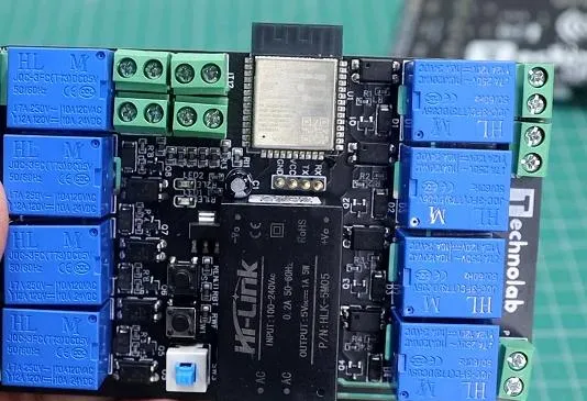
Custom PCBs also let you integrate multiple functions into a single board, reducing clutter and improving reliability. For instance, a single PCB can manage Wi-Fi connectivity, relay switching for appliances, and sensor data processing. By focusing on DIY home automation PCB projects, you can save money and gain valuable skills in electronics design.
Getting Started with DIY Home Automation PCB Projects
Starting a DIY home automation PCB project may seem daunting, but with the right approach, it’s achievable for beginners and pros alike. Here’s how to kick off your journey:
- Define Your Goal: Decide what you want to automate. Common projects include controlling lights, monitoring door sensors, or managing HVAC systems.
- Choose Components: Select microcontrollers like ESP32 or ESP8266 for Wi-Fi capabilities, relays for switching high-power devices, and sensors for data input (e.g., temperature sensors with a typical range of -40°C to 125°C).
- Plan Your Circuit: Sketch a basic circuit diagram to map out how components connect. This step is crucial for avoiding design errors.
Once you’ve outlined your project, the next step is to design the PCB layout. This brings us to selecting the right tools for home automation PCB design software.
Choosing the Best Home Automation PCB Design Software
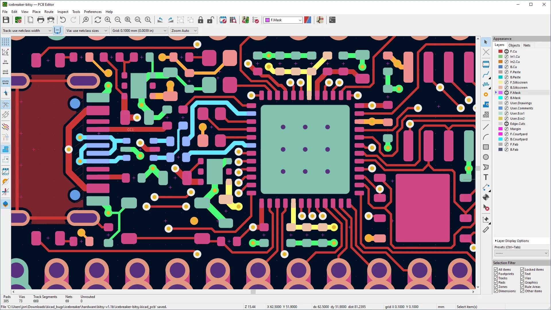
Designing a PCB requires software that lets you create schematics and layouts with precision. For home automation PCB design software, you’ll want tools that are user-friendly yet powerful enough to handle complex designs. Here are some key features to look for:
- Schematic Editor: To draw and simulate your circuit before building.
- PCB Layout Tools: For arranging components and routing traces with minimal signal interference.
- Component Libraries: Access to a wide range of parts like resistors, capacitors, and microcontrollers.
- Simulation Capabilities: To test impedance (typically in the range of 50-100 ohms for most traces) and signal integrity before manufacturing.
Many software options also support integration with manufacturing services, making it easy to order your boards once the design is complete. Look for tools that offer tutorials or community support to help with learning curves, especially if you’re new to PCB design.
Leveraging Open Source Home Automation PCB Schematics
If you’re not ready to design a PCB from scratch, open source home automation PCB schematics can be a fantastic starting point. These freely available designs are often shared by the maker community and can be modified to suit your needs. Here’s why they’re useful:
- Time-Saving: Use pre-designed schematics for common systems like relay boards or sensor hubs.
- Learning Opportunity: Study how experienced designers route traces and place components to avoid issues like crosstalk or heat buildup.
- Cost-Effective: Avoid the expense of professional design services by adapting existing files.
You can find open source schematics on platforms like GitHub or community forums dedicated to electronics. Always double-check the designs for errors and ensure they match your components’ specifications, such as voltage ratings (e.g., 3.3V or 5V for microcontrollers).
Building a Wireless Home Automation PCB
Wireless connectivity is at the heart of modern smart home systems, and building a wireless home automation PCB opens up endless possibilities. Here’s a step-by-step guide to creating a wireless PCB:
- Select a Wireless Module: Choose a module like ESP32, which supports Wi-Fi and Bluetooth with a typical operating frequency of 2.4 GHz.
- Design the Antenna Layout: Ensure proper trace length and impedance matching (often around 50 ohms) to avoid signal loss.
- Power Management: Include voltage regulators to provide a stable 3.3V supply to the wireless module, as fluctuations can disrupt connectivity.
- Testing: After assembly, test the board’s range and signal strength using tools like a spectrum analyzer to ensure reliable performance (aim for a signal strength above -70 dBm).
Wireless PCBs are ideal for controlling devices remotely via a smartphone app or integrating with voice assistants. Keep in mind that proper shielding is essential to prevent interference from other electronic devices in your home.
Home Automation PCB Troubleshooting: Common Issues and Fixes
Even with careful planning, issues can arise during or after building your PCB. Home automation PCB troubleshooting is a critical skill to ensure your project works as intended. Here are common problems and solutions:
- No Power to Components: Check for broken traces or cold solder joints. Use a multimeter to verify continuity and ensure input voltage (e.g., 5V or 12V) reaches all parts.
- Signal Interference: If your wireless module struggles to connect, inspect for crosstalk between traces. Reroute high-frequency signals away from power lines.
- Overheating: Excessive heat (above 85°C for most ICs) can damage components. Add heat sinks or improve airflow in your design.
- Firmware Bugs: If the board powers on but doesn’t function, debug the code uploaded to your microcontroller. Use serial monitoring to identify errors.
Troubleshooting often requires patience, but documenting each step can help you spot patterns and prevent future issues. Always test your board in small sections before full assembly to isolate problems early.
Home Automation PCB Power Supply Design: Ensuring Stability
A reliable power supply is the backbone of any smart home system, and home automation PCB power supply design deserves special attention. Poor power management can lead to system crashes or component damage. Follow these tips for a stable design:
- Voltage Regulation: Use linear or switching regulators to step down input voltage (e.g., from 12V to 5V) for microcontrollers and sensors.
- Current Capacity: Ensure your power supply can handle the total current draw. For example, a relay switching a 10A load requires a robust supply and thick traces (at least 1mm wide for high current).
- Noise Reduction: Add decoupling capacitors (typically 0.1μF near ICs) to filter out noise and stabilize voltage.
- Backup Power: Consider adding a small battery backup (like a 3.7V LiPo) for critical systems like security sensors.
Testing your power supply under full load is crucial. Use a multimeter to check for voltage drops (ideally below 0.2V) across key points on your board.
Secure Home Automation PCB Design: Protecting Your Smart Home
Smart home devices are often connected to the internet, making security a top priority. Secure home automation PCB design involves both hardware and software measures to protect against hacks. Here’s how to safeguard your system:
- Encrypted Communication: Use microcontrollers with built-in encryption for Wi-Fi data transmission, ensuring signals can’t be intercepted easily.
- Physical Protection: Add tamper-proof enclosures to prevent unauthorized access to your PCB.
- Firmware Security: Implement secure boot mechanisms and regular updates to patch vulnerabilities in your code.
- Power Isolation: Use optocouplers to separate high-voltage sections (like relay outputs) from low-voltage control circuits, reducing the risk of electrical faults affecting sensitive components.
Security is an ongoing process. Regularly monitor your network for unusual activity and keep backups of your firmware to recover quickly if something goes wrong.
Bringing It All Together: Manufacturing Your Custom PCB
Once your design is complete, it’s time to manufacture your PCB. Partner with a trusted fabrication service to ensure high-quality boards. Here’s what to consider:
- Design Files: Export your schematic and layout files in a standard format like Gerber for manufacturing.
- Material Choice: Opt for FR4 material for most home automation PCBs due to its durability and cost-effectiveness.
- Layer Count: Single or double-layer boards are usually sufficient for simple projects, keeping costs down.
- Testing: Order a small batch first to test functionality before full-scale production.
Manufacturing your PCB is the final step in turning your vision into reality. With platforms like ours at ALLPCB, you can streamline the process from design to delivery, ensuring your smart home automation project comes to life without hassle.
Conclusion: Power Up Your Smart Home Today
Building custom PCBs for smart home automation is an exciting and practical way to enhance your living space. By focusing on DIY home automation PCB projects, using the right home automation PCB design software, exploring open source home automation PCB schematics, and mastering skills like building a wireless home automation PCB, you can create tailored solutions that fit your needs perfectly.
Don’t forget the importance of home automation PCB troubleshooting, solid home automation PCB power supply design, and secure home automation PCB design to ensure reliability and safety. With the steps and tips provided in this guide, you’re well on your way to powering up your home with custom electronics. Start small, test often, and enjoy the process of bringing your smart home ideas to life!