 ALLPCB


If you're looking for a detailed resource on PCB form factor and mounting techniques, you've come to the right place. This guide will walk you through the essentials of designing and mounting printed circuit boards (PCBs), covering topics like PCB mounting hardware, enclosure design, mounting methods, standoff selection, and vibration-resistant techniques. Whether you're an engineer or a hobbyist, you'll find practical advice to ensure your PCB assemblies are secure, durable, and optimized for performance.
In the sections below, we'll dive deep into each aspect, providing actionable tips, specific examples, and best practices to help you achieve reliable PCB installations. Let's get started!
Understanding PCB Form Factor: The Foundation of Design
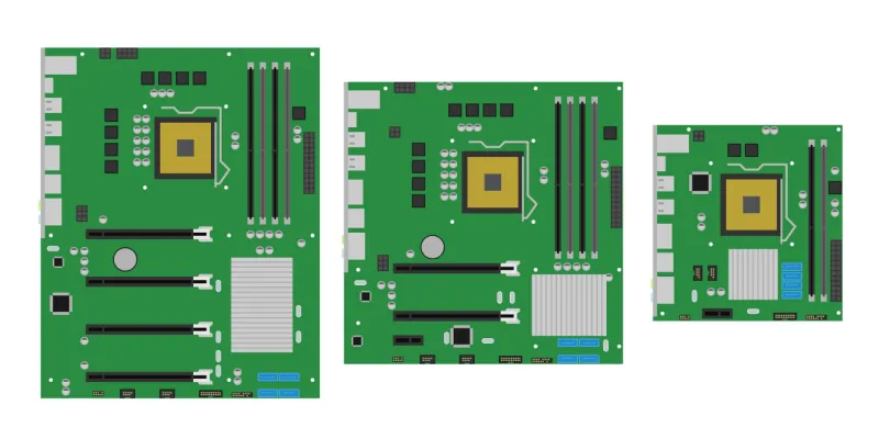
Before we explore mounting techniques, it's crucial to understand PCB form factor. The form factor refers to the physical size, shape, and layout of a PCB, which dictates how it fits into a device or enclosure. Choosing the right form factor ensures compatibility with your application and simplifies mounting.
Common PCB form factors include:
- ATX: Often used in desktop computers, measuring 12 x 9.6 inches (305 x 244 mm).
- Micro-ATX: A smaller variant at 9.6 x 9.6 inches (244 x 244 mm), ideal for compact systems.
- Mini-ITX: Even smaller at 6.7 x 6.7 inches (170 x 170 mm), used in small form factor PCs.
- Custom Sizes: Tailored to specific applications like wearables or IoT devices, often requiring unique mounting solutions.
Selecting a form factor involves considering space constraints, component placement, and thermal management. For instance, a larger PCB might offer more room for components but could complicate enclosure design. Always align the form factor with your project's mechanical and electrical requirements.
Related Reading: The Ultimate Guide to PCB Form Factors for Wearable Technology
Why PCB Mounting Matters
Proper PCB mounting is essential for the longevity and reliability of electronic devices. Without secure mounting, PCBs can suffer from mechanical stress, vibration damage, or poor thermal dissipation, leading to failures. Effective mounting also ensures safety, prevents short circuits, and maintains signal integrity, especially in high-frequency applications where impedance mismatches can degrade performance (e.g., maintaining 50-ohm impedance for RF signals).
Now, let's explore the key elements of PCB mounting, focusing on hardware, methods, and design considerations.
PCB Mounting Methods: Exploring Your Options
There are several PCB mounting methods to choose from, each suited to different applications. Below, we'll cover the most common techniques for securing a PCB within an enclosure or chassis.
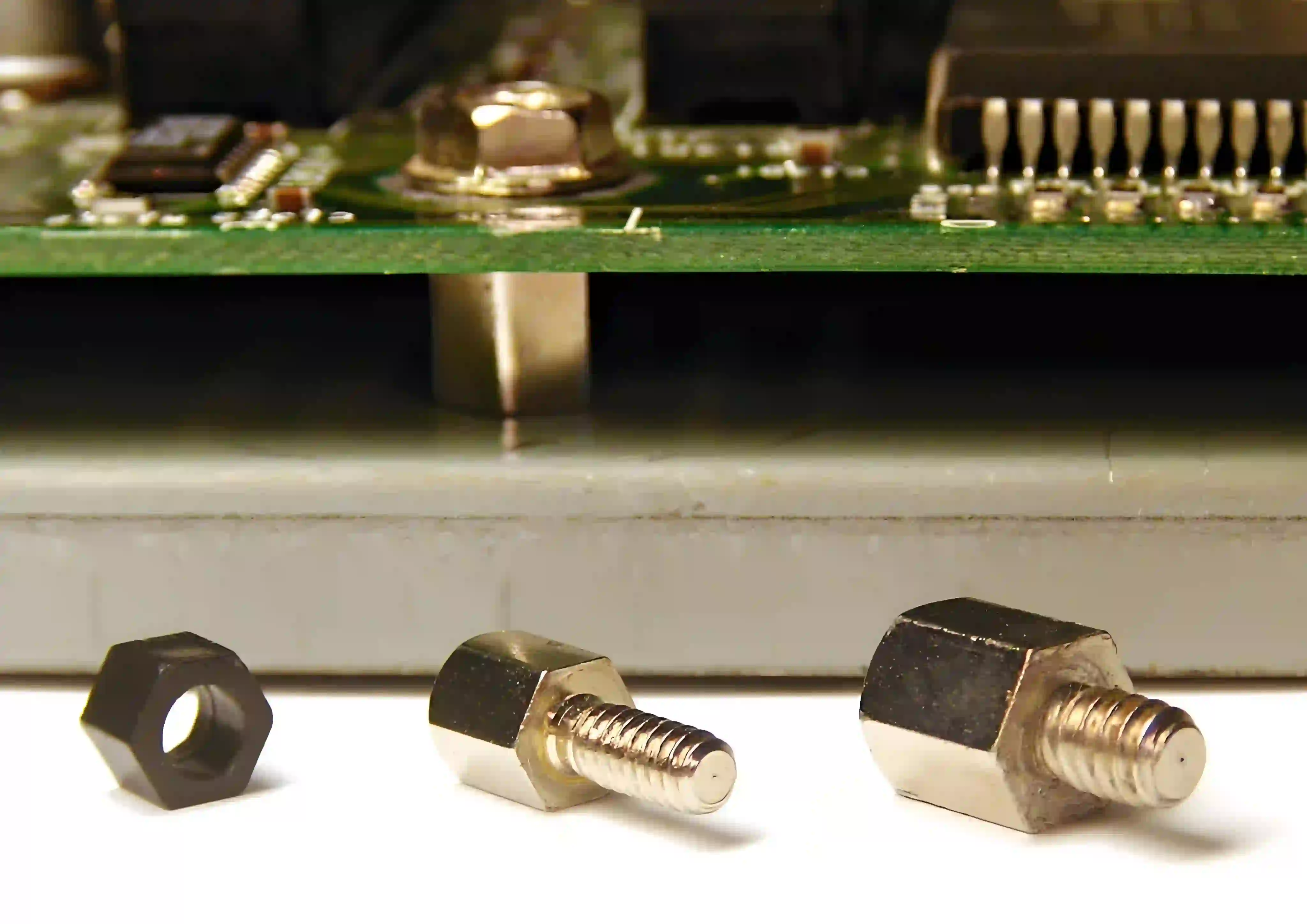
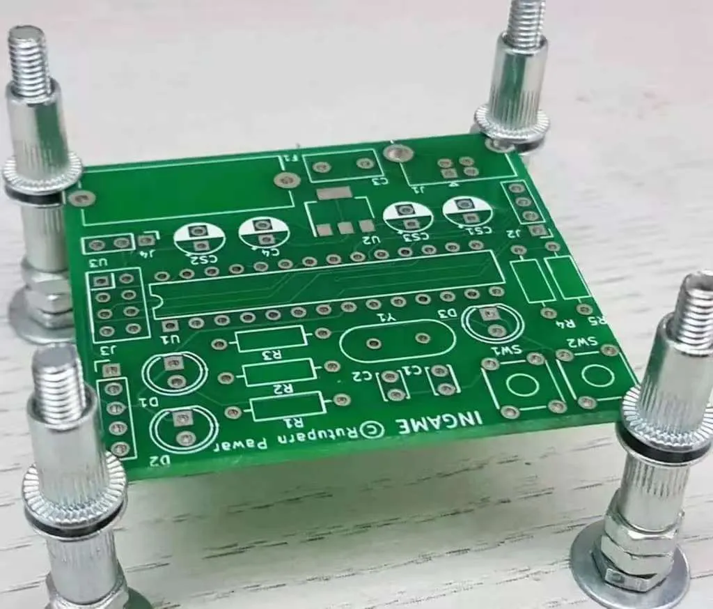
1. Screws with Standoffs
Using screws and standoffs is one of the most reliable PCB mounting methods. Standoffs are small spacers that elevate the PCB above the mounting surface, preventing short circuits and allowing airflow for cooling. Typically made of metal (brass or aluminum) or nylon, standoffs come in heights ranging from 0.125 inches (3.18 mm) to 1 inch (25.4 mm) or more.
Steps for Installation:
- Drill mounting holes in the PCB, usually 0.125 inches (3.18 mm) in diameter, matching the standoff thread size (e.g., M3 or 4-40).
- Attach standoffs to the enclosure or chassis.
- Place the PCB over the standoffs and secure with screws.
This method is ideal for industrial equipment where durability is key. However, it requires precise hole placement during PCB design.
2. Snap-In Plastic Clips
Snap-in clips offer a tool-free mounting solution, making them perfect for quick assembly or prototypes. These plastic holders clip onto the PCB edges or through mounting holes, securing it in place. They're lightweight and cost-effective but less robust than screws, so they're better for low-vibration environments.
3. Adhesive Pads
Adhesive mounting uses double-sided tape or glue to attach the PCB directly to a surface. This method is simple and works well for lightweight boards in confined spaces. However, it's not recommended for high-heat or vibration-prone applications as adhesives can degrade over time, losing their hold.
4. Rail Systems (e.g., DIN Rails)
DIN rail mounting is common in industrial control systems. The PCB is housed in a module that clips onto a standardized rail, allowing easy installation and removal. This method is excellent for modular designs but may require additional enclosure considerations.
PCB Mounting Hardware: Choosing the Right Tools
Selecting the appropriate PCB mounting hardware is just as important as the mounting method. Here's a breakdown of common hardware options and their uses.
Screws and Nuts
Screws are typically made of stainless steel or brass for corrosion resistance. Common sizes include M2, M3, or 4-40 threads, with lengths varying based on PCB thickness and standoff height. Torque specifications are critical—over-tightening can crack the PCB. A typical torque value for M3 screws on a PCB is 0.5-0.6 Nm.
Standoffs and Spacers
As mentioned earlier, standoffs prevent electrical shorts and improve airflow. When selecting standoffs, consider:
- Material: Metal for grounding or nylon for insulation.
- Height: Ensure clearance for components underneath (e.g., 0.25 inches or 6.35 mm for small capacitors).
- Thread Size: Match with screws for secure fastening.
Mounting Clips and Brackets
Clips and brackets provide additional support, especially for larger PCBs. They can be custom-designed to fit specific board shapes, ensuring a snug fit within the enclosure.
PCB Standoff Selection: Key Factors to Consider
Proper PCB standoff selection can make or break your design. Here are the main factors to evaluate:
- Height: Choose a height that provides enough clearance for components and heat dissipation. For example, a PCB with tall electrolytic capacitors may need a 0.5-inch (12.7 mm) standoff.
- Material: Use conductive standoffs (e.g., brass) if grounding is needed, or insulating materials (e.g., nylon) to avoid shorts.
- Load Capacity: Ensure the standoff can support the PCB's weight, especially in vibration-heavy environments.
- Environment: For outdoor or harsh conditions, select corrosion-resistant materials like stainless steel.
By carefully matching standoffs to your design needs, you can avoid issues like board flexing or insufficient cooling.
PCB Enclosure Design: Protecting Your Board
A well-designed enclosure not only protects the PCB from dust, moisture, and physical damage but also aids in mounting and thermal management. Here’s how to approach PCB enclosure design:
Material Selection
Enclosures are typically made of plastic (e.g., ABS or polycarbonate) for lightweight applications or metal (e.g., aluminum) for rugged environments. Metal enclosures also help with electromagnetic interference (EMI) shielding, critical for high-frequency circuits operating at 2.4 GHz or above.
Size and Fit
Ensure the enclosure is slightly larger than the PCB to accommodate mounting hardware and wiring. For example, leave at least 0.1 inches (2.54 mm) of clearance on all sides to prevent stress on the board.
Ventilation and Cooling
Design vents or slots for airflow, especially if the PCB generates heat (e.g., power supply circuits with 10W or more dissipation). Fans or heat sinks may be necessary for high-power applications.
Mounting Points
Integrate mounting points directly into the enclosure design, such as bosses for screws or slots for snap-in clips. This simplifies assembly and ensures a secure fit.
Related Reading: Thermal Considerations in PCB Form Factor Design: Keeping Your Circuits Cool
Vibration-Resistant PCB Mounting: Ensuring Durability
In applications like automotive or industrial machinery, vibration can loosen mounts or damage components. Vibration-resistant PCB mounting techniques are crucial for reliability in such environments.
Use Locking Hardware
Opt for screws with locking washers or thread-locking compounds to prevent loosening. Nylon-insert lock nuts are also effective, maintaining grip even under constant vibration.
Rubber or Silicone Dampers
Incorporate rubber grommets or silicone pads between the PCB and mounting surface to absorb vibrations. These dampers can reduce mechanical stress by up to 50%, based on typical industrial testing.
Reinforce Mounting Points
For high-vibration settings, use additional mounting points or brackets to distribute stress evenly across the PCB. Avoid placing mounts only at corners, as this can cause flexing in the center.
Secure Component Placement
Ensure heavy components (e.g., transformers) are secured with adhesive or additional fasteners to prevent them from detaching during vibration. This is especially important for boards experiencing frequencies of 10-100 Hz.
Best Practices for PCB Mounting and Design
To wrap up, here are some best practices to ensure your PCB mounting is both effective and reliable:
- Plan Mounting Early: Include mounting holes and standoff locations in the initial PCB layout to avoid redesigns.
- Test for Stress: Simulate vibration and thermal conditions to identify weak points in your mounting setup.
- Consider Accessibility: Ensure screws or clips are easy to reach for maintenance or upgrades.
- Follow Standards: Adhere to industry standards like IPC-A-610 for acceptable mounting practices, ensuring quality and safety.
Conclusion: Mastering PCB Form Factor and Mounting
Understanding PCB form factor and mounting techniques is vital for creating robust and efficient electronic designs. From selecting the right mounting hardware to designing a protective enclosure, each step plays a role in ensuring your PCB performs reliably under various conditions. By focusing on details like standoff selection and vibration-resistant mounting, you can avoid common pitfalls and extend the lifespan of your assemblies.
Whether you're working on a small prototype or a large-scale industrial project, applying the insights from this guide will help you achieve secure and professional PCB installations. Keep these tips in mind as you design and mount your next board, and you'll be well on your way to success.


