 ALLPCB


Setting up a basic PCB testing lab at home is an achievable goal for electronics enthusiasts, hobbyists, and even small-scale engineers looking to test and debug printed circuit boards (PCBs) without relying on expensive professional facilities. Whether you're troubleshooting a prototype or ensuring the quality of a small batch of boards, a home PCB testing setup can save time and money. In this comprehensive guide, we'll walk you through the process of creating a PCB testing workspace, highlight the essential tools for PCB testing, and provide actionable tips for setting up equipment like a multimeter for PCB testing. By the end, you'll have a clear roadmap to build a functional and efficient testing lab right at home.
Why Set Up a Home PCB Testing Lab?
Before diving into the details of a home PCB testing setup, it’s important to understand the benefits. Testing PCBs at home allows you to catch issues early in the design or assembly process, reducing the risk of costly errors. It also offers flexibility, as you can work on your projects at your own pace without waiting for third-party testing services. Additionally, a home lab fosters learning and experimentation, helping you build skills in electronics troubleshooting and repair. With the right tools and workspace, you can achieve reliable results comparable to professional setups on a smaller scale.
Step 1: Planning Your PCB Testing Workspace
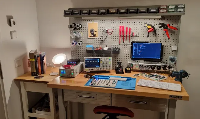
Creating a PCB testing workspace is the foundation of an effective home lab. Your workspace should be safe, organized, and conducive to focused work. Here’s how to get started:
- Choose a Dedicated Area: Select a quiet, well-lit space in your home, such as a spare room, garage, or a corner of your office. Ensure the area is free from distractions and has access to power outlets.
- Work Surface: Use a sturdy desk or workbench with a non-conductive surface to prevent accidental short circuits. A surface area of at least 3x2 feet (approximately 90x60 cm) is ideal for most small-scale PCB testing tasks.
- Lighting: Invest in good lighting, such as an adjustable desk lamp with a magnifying lens. This helps when inspecting small components or solder joints on a PCB, which can be as tiny as 0.5 mm in size for surface-mount devices (SMDs).
- Ventilation: If you’re soldering or desoldering as part of testing, ensure proper ventilation to avoid inhaling fumes. A small exhaust fan or a fume extractor is a worthwhile addition.
- Storage: Use organizers or small drawers to store tools, components, and PCBs. Keeping everything within reach saves time and reduces clutter.

Step 2: Essential Tools for PCB Testing
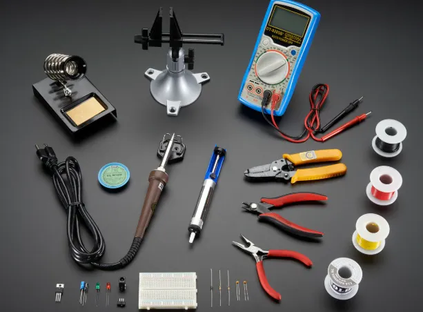
Having the right tools is critical for effective PCB testing. Below is a basic PCB testing equipment list to help you build a functional home lab. These tools are affordable and cover most testing needs for hobbyists and small projects.
1. Multimeter
A multimeter is the cornerstone of any PCB testing setup. It measures voltage, current, and resistance, helping you diagnose issues like short circuits, open connections, or incorrect component values. A decent digital multimeter costs between $20 and $50 and should have a resolution of at least 0.1 mV for voltage measurements to detect small variations in PCB signals.
2. Power Supply
A variable DC power supply (0-30V, 0-5A) is essential for powering your PCB during testing. Look for one with adjustable voltage and current limiting features to prevent damage to your board. Expect to spend around $50 to $100 for a reliable unit.
3. Oscilloscope (Optional but Useful)
For more advanced testing, an oscilloscope helps visualize signal waveforms, making it easier to debug issues with timing or noise. Entry-level digital oscilloscopes start at around $200, with bandwidths of 50 MHz being sufficient for most hobbyist needs.
4. Soldering and Desoldering Tools
A soldering iron (25-40W) with a fine tip is necessary for fixing or replacing components during testing. Pair it with a desoldering pump or wick to remove solder. A basic soldering kit costs about $15 to $30.
5. Magnifying Glass or Microscope
Inspecting tiny solder joints or component markings requires magnification. A handheld magnifying glass or a USB microscope (costing $20 to $50) with 10x to 50x zoom is ideal for detailed work.
6. Test Probes and Clips
Alligator clips, hook probes, and needle probes make it easier to connect your multimeter or oscilloscope to specific points on the PCB. A set of these costs around $10 to $20.
7. Breadboard and Jumper Wires
For prototyping or testing circuits before soldering them onto a PCB, a breadboard and a set of jumper wires are invaluable. These are cheap, typically under $10 for a small kit.
8. Component Tester
A small handheld component tester can quickly identify and measure resistors, capacitors, and transistors, saving time during troubleshooting. These devices cost between $15 and $30.
Step 3: Setting Up a Multimeter for PCB Testing
A multimeter is one of the most versatile tools in your home PCB testing setup, but using it correctly is key to accurate results. Here’s a step-by-step guide to setting up and using a multimeter for PCB testing:
- Select the Right Mode: Depending on what you’re testing, set the multimeter to the appropriate mode—DC voltage (VDC) for checking power rails, resistance (Ω) for continuity tests, or current (A) for measuring power draw. For example, when testing a 5V power line on a PCB, set the multimeter to VDC with a range above 5V (e.g., 20V).
- Connect the Probes: Insert the black probe into the COM (common) port and the red probe into the V/Ω port for voltage and resistance measurements. For current, use the dedicated current port (often labeled 10A or mA).
- Test Continuity: To check for short circuits or broken traces, switch to continuity mode (if available) or the lowest resistance range. Touch the probes to two points on the PCB; a beep or low resistance reading (close to 0 Ω) indicates a connection.
- Measure Voltage: Place the black probe on a ground point (GND) and the red probe on the test point to measure voltage. For instance, a typical microcontroller PCB might show 3.3V or 5V on power pins.
- Safety First: Always power off the PCB before connecting probes for resistance or continuity tests to avoid damaging the multimeter or the board.
Step 4: Basic PCB Testing Methods for Home Labs
With your workspace and tools ready, it’s time to apply some basic PCB testing techniques. These methods will help you identify common issues like shorts, opens, or incorrect component behavior.
Visual Inspection
Start with a thorough visual check under good lighting and magnification. Look for obvious issues like cracked solder joints, misaligned components, or burn marks. For SMD components, ensure pads are properly soldered with no cold joints (dull, uneven solder).
Continuity Testing
Use your multimeter to verify that traces and connections are intact. Test between component pads and corresponding traces to ensure there are no breaks. A reading of infinite resistance indicates an open circuit.
Power-On Testing
Connect your PCB to a power supply set to the correct voltage (e.g., 5V for many hobbyist boards). Use the multimeter to confirm that power reaches key points like IC pins or voltage regulators. If a section shows 0V, trace back to find the issue.
Component Testing
Remove and test individual components if you suspect they’re faulty. For example, a capacitor with a rated value of 10 μF should read close to that on a component tester. Deviations of more than 10-20% might indicate a problem.
Step 5: Safety Tips for Your Home PCB Testing Lab
Safety should always be a priority when working with electronics. Follow these tips to protect yourself and your equipment:
- Avoid High Voltages: Stick to low-voltage projects (under 30V) unless you have proper training and insulated tools.
- Use Anti-Static Protection: Wear an anti-static wrist strap or work on an anti-static mat to prevent electrostatic discharge (ESD) from damaging sensitive components. ESD can occur with voltages as low as 100V, which is imperceptible to humans but deadly to ICs.
- Keep Tools Insulated: Ensure your soldering iron and probes have insulated handles to avoid accidental shocks.
- Power Off Before Testing: Always disconnect power before probing for continuity or resistance to prevent shorting components.
Step 6: Budgeting for Your Home PCB Testing Setup
Building a basic PCB testing lab at home doesn’t have to break the bank. Here’s a rough cost estimate for the essential tools:
| Tool | Approximate Cost (USD) |
|---|---|
| Digital Multimeter | 20-50 |
| Variable Power Supply | 50-100 |
| Soldering Kit | 15-30 |
| Magnifying Glass/USB Microscope | 20-50 |
| Test Probes and Clips | 10-20 |
| Breadboard and Wires | 5-10 |
| Component Tester | 15-30 |
| Total | 135-290 |
This budget range allows you to start with the basics and scale up as needed. Adding an oscilloscope later will increase the cost but also expand your testing capabilities.
Conclusion: Start Testing PCBs at Home with Confidence
Setting up a basic PCB testing lab at home is a rewarding endeavor that empowers you to troubleshoot, debug, and perfect your electronics projects. By carefully planning your workspace, investing in essential tools for PCB testing, and following proper techniques like setting up a multimeter for PCB testing, you can achieve professional-grade results on a budget. Start small with the basic PCB testing equipment list provided, prioritize safety, and gradually expand your setup as your skills and projects grow. With dedication and the right tools, your home PCB testing setup will become an invaluable asset in your electronics journey.


