 ALLPCB


Are you looking to create a heart rate monitor PCB project from scratch? Whether you're a hobbyist or a beginner in electronics, this guide will walk you through the process of designing and building a simple heart rate monitor using an Arduino heart rate sensor and a custom PCB. We'll cover everything from the basics of heart rate sensing to DIY PCB fabrication, PCB etching at home, and soldering components PCB. By the end of this blog, you'll have a functional device to measure heart rate and a solid understanding of custom PCB creation.
Why Build a Heart Rate Monitor with a Custom PCB?
Building a heart rate monitor is an excellent project for beginners in electronics. It combines sensor technology, microcontroller programming, and PCB design into one hands-on experience. Using a custom PCB instead of a breadboard makes your project more compact, reliable, and professional. Plus, learning skills like DIY PCB fabrication and soldering components PCB opens doors to more advanced projects. This guide is tailored for those who are new to electronics but eager to dive into a rewarding heart rate monitor PCB project.
What You'll Need for This Project
Before we get started, let’s gather the necessary tools and components. Having everything ready will make the process smoother and more enjoyable.
- Arduino Board: A microcontroller board like the Arduino Uno to process sensor data.
- Heart Rate Sensor: A pulse sensor module (commonly available as an optical sensor) for detecting heartbeats.
- Resistors and Capacitors: Basic components for filtering and stabilizing the sensor signal (specific values like 1kΩ resistors and 0.1μF capacitors will be discussed later).
- LED and Display (Optional): For visual output of heart rate data, such as a simple OLED screen or LED indicator.
- PCB Materials: Copper-clad board, ferric chloride for etching, and a permanent marker or laser printer for transferring the design.
- Soldering Tools: Soldering iron, solder wire, and flux for soldering components PCB.
- Design Software: Free tools like KiCad or Fritzing to create your PCB layout.
- Basic Tools: Drill for PCB holes, multimeter for testing, and safety gear like gloves and goggles for PCB etching at home.
Step 1: Understanding How a Heart Rate Monitor Works
A heart rate monitor measures the number of heartbeats per minute (BPM) by detecting changes in blood flow. Most beginner-friendly sensors use optical technology, where a light source (like an LED) shines through your skin, and a photodiode detects variations in light intensity caused by blood flow. The Arduino heart rate sensor processes this data and converts it into a readable BPM value.
The typical pulse sensor operates with a signal frequency range of 0.5Hz to 4Hz, corresponding to heart rates of 30 to 240 BPM. The Arduino reads this analog signal, applies a threshold or algorithm to count pulses, and outputs the result. Understanding this basic principle helps in designing the circuit and PCB layout for your heart rate monitor PCB project.
Step 2: Designing the Circuit for Your Heart Rate Monitor
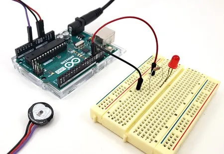
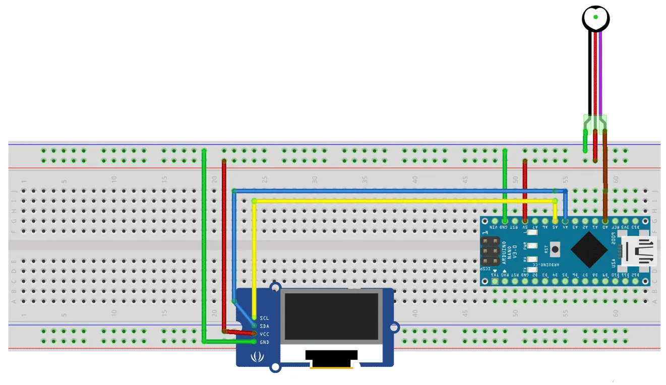
Start by designing a simple circuit that connects the heart rate sensor to the Arduino. The sensor typically has three pins: VCC (power, usually 3.3V or 5V), GND (ground), and Signal (analog output). Connect VCC to the Arduino’s 5V pin, GND to GND, and the Signal pin to an analog input pin like A0.
To clean up noise in the signal, add a simple RC filter. Use a 1kΩ resistor in series with the signal line and a 0.1μF capacitor to ground. This setup helps reduce high-frequency noise, ensuring more accurate readings. Once the circuit is planned, test it on a breadboard before moving to PCB design.
Step 3: Creating a Custom PCB Layout
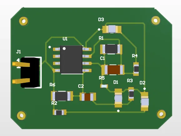
Now that your circuit works on a breadboard, it’s time for DIY PCB fabrication. Designing a custom PCB makes your project more durable and compact. Follow these steps to create your PCB layout:
- Choose a Design Software: Use a free tool like KiCad to draw your schematic and convert it into a PCB layout. Place the Arduino, sensor, and components strategically to minimize trace length.
- Define Traces and Pads: Ensure traces are wide enough (at least 0.25mm) to handle current without breaking. Keep power and ground traces separate to avoid interference.
- Export the Design: Once your layout is ready, print it on glossy paper using a laser printer or draw it with a permanent marker for manual transfer.
The goal is to create a clean, functional design that connects all components efficiently. If you're new to PCB design, keep it simple by using a single-layer board for this heart rate monitor PCB project.
Step 4: PCB Etching at Home
PCB etching at home is a cost-effective way to create custom boards without expensive equipment. Here’s how to do it safely and effectively:
- Prepare the Copper Board: Clean a copper-clad board with steel wool to remove oxidation. This ensures the toner or marker adheres properly.
- Transfer the Design: If using a laser printer, iron the printed design onto the board. For manual designs, draw directly with a permanent marker. The black lines will protect the copper during etching.
- Etch the Board: Mix ferric chloride solution (follow safety instructions on the package) in a plastic container. Submerge the board for 10-20 minutes, agitating occasionally. Unprotected copper will dissolve, leaving your traces.
- Clean and Drill: Rinse the board with water, remove the toner or marker with acetone, and drill holes for components using a small hand drill (0.8mm to 1mm bits work for most components).
Safety is crucial during PCB etching at home. Wear gloves, goggles, and work in a well-ventilated area to avoid contact with chemicals. Dispose of the etching solution responsibly according to local regulations.
Step 5: Soldering Components to Your PCB
With your custom PCB ready, it’s time for soldering components PCB. Soldering can seem intimidating, but with practice, it becomes straightforward. Follow these tips for a clean job:
- Prepare Your Tools: Heat your soldering iron to around 300°C (572°F) for standard components. Use a fine tip for precision.
- Insert Components: Place components through the drilled holes according to your layout. Start with smaller parts like resistors and capacitors before larger ones like the sensor module.
- Solder Joints: Apply a small amount of solder to the iron tip, then touch it to the pad and component lead simultaneously. The solder should flow smoothly, forming a shiny cone. Avoid excess solder to prevent shorts.
- Inspect and Test: Check for cold joints (dull, uneven solder) and use a multimeter to ensure connections are secure.
Take your time with soldering, as mistakes can damage components or the board. If a joint looks off, reheat it and adjust. This step is critical for a reliable heart rate monitor PCB project.
Step 6: Programming the Arduino for Heart Rate Monitoring
With the hardware assembled, program your Arduino to read data from the Arduino heart rate sensor. Here’s a basic approach to get started:
- Install Libraries: Download a pulse sensor library (available in the Arduino IDE library manager) to simplify signal processing.
- Write the Code: Use example code from the library to read analog values from the sensor pin (e.g., A0). The library often includes algorithms to calculate BPM by detecting peaks in the signal.
- Output the Data: Send BPM values to the Serial Monitor in the Arduino IDE or display them on an OLED screen if you’ve added one.
A typical threshold for detecting a heartbeat peak might be around 550-600 on the analog scale (0-1023 for Arduino’s 10-bit ADC). Adjust this value based on testing to improve accuracy. Upload the code and test the setup by placing your finger on the sensor.
Step 7: Testing and Troubleshooting Your Heart Rate Monitor
After assembling and programming, test your heart rate monitor by placing your finger on the sensor. You should see BPM readings between 60 and 100 for a resting adult. If the readings are inconsistent or absent, troubleshoot using these tips:
- Check Sensor Placement: Ensure the sensor is in firm contact with your skin, ideally on a fingertip or earlobe.
- Inspect Connections: Verify all soldered joints and wiring. Loose connections can cause signal loss.
- Adjust Code Parameters: If readings are erratic, tweak the threshold value in your code to better detect peaks.
- Reduce Noise: If external light or movement interferes, shield the sensor or add a stronger filter circuit.
Testing ensures your heart rate monitor PCB project works reliably before using it regularly.
Step 8: Enhancing Your Heart Rate Monitor
Once your basic monitor works, consider upgrades to make it more user-friendly or feature-rich:
- Add a Display: Integrate a small OLED screen to show BPM without needing a computer.
- Bluetooth Connectivity: Use a Bluetooth module to send data to a smartphone app for logging.
- Enclosure: Design a 3D-printed case to protect the PCB and make the device portable.
These enhancements build on the skills you’ve learned, from DIY PCB fabrication to programming, and make your project stand out.
Conclusion: Your First Step into Custom Electronics
Building a heart rate monitor with a custom PCB is a fantastic way to learn about electronics, from designing circuits to PCB etching at home and soldering components PCB. This heart rate monitor PCB project not only teaches practical skills but also results in a functional device you can use for fitness or educational purposes. By following this guide, you’ve taken a significant step into the world of custom electronics with an Arduino heart rate sensor.
Start small, be patient with each step, and soon you’ll be ready for more complex projects. The skills you’ve gained here—circuit design, PCB creation, and programming—are the foundation for countless innovations. Keep experimenting, and let your creativity guide your next build!


