 ALLPCB


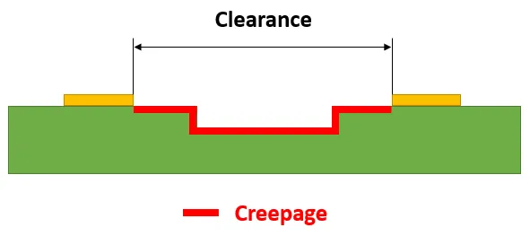
In high-speed PCB design, the clearance between traces plays a critical role in maintaining signal integrity. Insufficient spacing can lead to crosstalk, electromagnetic interference (EMI), and impedance mismatches, all of which degrade performance. By carefully managing trace clearance, designers can ensure clean signal transmission, minimize interference, and optimize the return path for high-speed signals. In this blog, we’ll dive deep into how trace clearance impacts signal integrity and provide actionable tips for achieving reliable performance in your designs.
What Is Signal Integrity in High-Speed PCB Design?
Signal integrity refers to the quality of an electrical signal as it travels through a printed circuit board (PCB). In high-speed PCB design, where signals switch at frequencies often exceeding 100 MHz, maintaining signal integrity becomes challenging. Issues like crosstalk, reflections, and EMI can distort signals, leading to data errors or system failures. Factors such as trace impedance, return path continuity, and trace clearance directly influence how well a signal maintains its shape and timing.
Trace clearance, or the spacing between adjacent traces, is often overlooked but is vital for preventing interference. When traces are too close, the electric and magnetic fields around them can couple, causing unwanted noise. This is especially problematic in high-speed designs where signals are more sensitive to disturbances. Let’s explore how trace clearance impacts key aspects of signal integrity and what you can do to optimize it.
Why Trace Clearance Matters for Signal Integrity
In high-speed PCBs, signals travel as electromagnetic waves along traces, and their behavior is influenced by the surrounding environment. The clearance between traces affects the electric field distribution and can introduce parasitic effects. Here are the primary reasons why trace clearance is critical:
- Crosstalk Reduction: Crosstalk occurs when a signal on one trace induces noise on a nearby trace due to electromagnetic coupling. Wider clearance reduces this coupling, lowering the risk of signal distortion.
- Impedance Control: Trace impedance, which determines how a signal propagates, can be affected by nearby traces. Proper spacing helps maintain consistent impedance, avoiding reflections that degrade signal quality.
- EMI Mitigation: Electromagnetic interference can radiate from traces or be picked up from external sources. Adequate clearance minimizes the loop area for current return paths, reducing EMI.
- Return Path Integrity: High-speed signals require a continuous return path, often through a ground plane. Close traces can disrupt this path, leading to signal delays or noise.
How Trace Clearance Impacts Crosstalk in High-Speed PCB Design
Crosstalk is one of the most common issues in high-speed PCB design, and trace clearance directly influences its severity. There are two types of crosstalk: near-end (NEXT) and far-end (FEXT). NEXT occurs when noise is induced at the source end of a trace, while FEXT happens at the receiving end. Both are caused by electromagnetic coupling between traces, and the closer the traces, the stronger the coupling.
For example, at frequencies above 1 GHz, a clearance of less than 3 times the trace width can result in significant crosstalk. A general rule of thumb is the "3W rule," which suggests maintaining a clearance of at least three times the trace width to minimize coupling. If a trace is 5 mils wide, the clearance should be at least 15 mils. This spacing reduces the electric field overlap, keeping signals isolated.
In practice, achieving this spacing isn’t always possible due to board size constraints. In such cases, designers can use differential pair routing or add ground traces between high-speed signals to act as shields. However, increasing clearance remains the most effective and simplest solution for reducing crosstalk.
Trace Clearance and Trace Impedance: A Balancing Act
Trace impedance is a measure of how a trace resists the flow of high-frequency signals. It’s determined by factors like trace width, thickness, dielectric material, and proximity to other traces or planes. In high-speed PCB design, maintaining a consistent impedance—often 50 ohms for single-ended signals or 100 ohms for differential pairs—is essential to prevent signal reflections.
When traces are placed too close together, the electric field from one trace can interact with another, altering the effective impedance. For instance, a 50-ohm trace might see its impedance drop to 45 ohms if a neighboring trace is too close, causing mismatches. Reflections from impedance mismatches can lead to signal ringing or loss of data integrity.
To avoid this, designers must calculate the required clearance based on the target impedance and board stack-up. Tools like impedance calculators or field solvers can help determine the optimal spacing. As a general guideline, maintaining a clearance equal to or greater than the trace width helps stabilize impedance, though this may vary based on the dielectric constant of the PCB material (typically 4.2 for FR-4).
The Role of Trace Clearance in Managing Electromagnetic Interference (EMI)
Electromagnetic interference is a major concern in high-speed PCB design, as it can disrupt not only the board’s operation but also nearby devices. EMI often results from high-frequency signals radiating energy through traces acting as antennas. The clearance between traces influences the loop area formed by the signal and its return path, which directly impacts EMI.
A smaller loop area reduces the amount of radiated energy, minimizing EMI. By increasing trace clearance, especially between signal traces and power or ground lines, you can control the loop area more effectively. Additionally, proper spacing prevents signals from coupling into power lines, which can act as conduits for noise across the board.
For example, in a design operating at 2.5 GHz, reducing the clearance between a signal trace and a power trace from 20 mils to 5 mils can increase EMI by up to 30%. To combat this, ensure adequate spacing and consider using ground planes or shielding vias to contain electromagnetic fields.
Return Path Continuity and Trace Clearance
In high-speed PCB design, every signal needs a return path to complete the circuit. For high-frequency signals, this path is typically through a ground plane directly beneath the trace. If traces are too close together, or if the return path is interrupted by splits in the ground plane, the signal may take a longer, less direct route. This increases inductance, delays the signal, and introduces noise.
Trace clearance affects how cleanly the return path flows. When traces are tightly packed, the return current may crowd into a smaller area, increasing resistance and inductance. A practical solution is to maintain a clearance that allows return currents to spread evenly across the ground plane. A spacing of at least 2-3 times the trace width is often sufficient, though this depends on the signal speed and board layout.
Additionally, avoid routing high-speed traces over splits in ground planes, as this forces the return path to detour, creating EMI and signal integrity issues. If tight spacing is unavoidable, consider adding stitching vias to connect ground planes and provide a shorter return path.
Practical Tips for Optimizing Trace Clearance in High-Speed PCBs
Now that we understand how trace clearance impacts signal integrity, let’s look at some practical strategies to optimize it in your designs. These tips are tailored for high-speed PCB design and focus on maintaining clean signals while addressing constraints like board size and cost.
- Follow the 3W Rule for Spacing: As mentioned earlier, keep a clearance of at least three times the trace width between high-speed traces to reduce crosstalk. For a 6-mil trace, aim for an 18-mil clearance.
- Use Differential Pair Routing: For critical high-speed signals, route them as differential pairs with consistent spacing. This minimizes external interference and maintains impedance.
- Prioritize Ground Planes: Ensure a continuous ground plane beneath high-speed traces to provide a low-impedance return path. Avoid routing traces over gaps or splits.
- Calculate Impedance with Tools: Use simulation software to model trace impedance based on clearance, width, and dielectric properties. Adjust spacing to match the target impedance (e.g., 50 ohms).
- Separate High-Speed and Low-Speed Signals: Keep high-speed traces away from slower signals or power lines to prevent EMI. If spacing is limited, use ground traces as barriers.
- Test and Iterate: After layout, simulate the design for signal integrity issues like crosstalk or reflections. Adjust clearance as needed based on simulation results.
Common Mistakes to Avoid with Trace Clearance
Even experienced designers can make errors when managing trace clearance in high-speed PCB design. Here are some common pitfalls and how to steer clear of them:
- Ignoring Clearance for Density: Sacrificing clearance to fit more traces on a board often leads to crosstalk and EMI. Always prioritize signal integrity over density.
- Inconsistent Spacing: Uneven clearance between traces can cause impedance variations. Maintain uniform spacing across the board, especially for critical signals.
- Neglecting Return Paths: Failing to account for return path disruptions due to tight spacing can degrade performance. Use vias or additional ground layers if needed.
- Overlooking Material Effects: The dielectric constant of the PCB material affects how clearance impacts impedance. Factor this into your calculations, especially for frequencies above 1 GHz.
Conclusion: Mastering Trace Clearance for Better Signal Integrity
In high-speed PCB design, every detail matters, and trace clearance is no exception. Proper spacing between traces is essential for minimizing crosstalk, controlling trace impedance, reducing electromagnetic interference, and ensuring a clean return path. By following guidelines like the 3W rule, using continuous ground planes, and leveraging simulation tools, you can optimize clearance to achieve reliable signal integrity.
Whether you’re designing for data rates of 1 Gbps or 10 Gbps, paying attention to trace clearance can make the difference between a functional board and one plagued by noise and errors. Take the time to plan your layout carefully, test your design, and adjust as needed. With these strategies, you’ll be well-equipped to tackle the challenges of high-speed PCB design and deliver top-performing circuits.


