ALLPCB


Are you struggling to design high-speed PCBs for automotive infotainment systems that maintain signal integrity and minimize EMI? You're not alone. Designing PCBs for infotainment systems requires balancing high-speed data transfer, strict signal integrity, and electromagnetic interference (EMI) reduction while meeting the compact and cost-effective demands of automotive applications. In this comprehensive guide, we’ll uncover the secrets of high-speed PCB layout infotainment design, focusing on signal integrity infotainment PCB, EMI reduction infotainment system, and impedance control PCB design. Whether you're an electrical engineer working on next-gen infotainment systems or looking to optimize your PCB designs, this post will provide actionable insights to elevate your work.
Why High-Speed PCB Design Matters for Infotainment Systems
Automotive infotainment systems are the heart of modern vehicles, integrating navigation, entertainment, connectivity, and driver assistance features into a single interface. These systems rely on high-speed data transmission to handle video streaming, real-time GPS updates, and communication protocols like USB 3.0, HDMI, and Ethernet. With data rates often exceeding 5 Gbps, even small design flaws in the PCB can lead to signal degradation, crosstalk, or EMI issues that disrupt system performance.
High-speed PCB design for infotainment systems isn’t just about speed—it’s about reliability under harsh automotive conditions. Temperature swings, vibrations, and strict regulatory standards for electromagnetic compatibility (EMC) add layers of complexity. A poorly designed PCB can result in costly redesigns, delayed product launches, or even safety risks if critical systems fail. Let’s dive into the key principles and secrets to mastering high-speed PCB layout infotainment design.

Secret 1: Prioritize Signal Integrity in Infotainment PCB Design
Signal integrity is the foundation of any high-speed PCB, especially for infotainment systems where data must travel without distortion. Signal integrity infotainment PCB design ensures that signals maintain their shape and timing as they move through traces, connectors, and components. Poor signal integrity can cause data errors, jitter, or complete system failure.
Key Strategies for Signal Integrity:
- Minimize Trace Lengths: Keep high-speed signal traces as short as possible to reduce signal delay and attenuation. For example, USB 3.0 signals operating at 5 Gbps should ideally have trace lengths under 6 inches to avoid significant loss.
- Use Differential Pairs: High-speed protocols like HDMI and LVDS (Low-Voltage Differential Signaling) used in infotainment systems rely on differential pairs. Ensure these traces are matched in length (within 5 mils) to prevent skew and maintain signal timing.
- Avoid Sharp Corners: Route traces with 45-degree angles instead of 90-degree turns to prevent signal reflections caused by impedance discontinuities.
One real-world challenge I’ve encountered is designing for high-speed video signals in infotainment displays. A project I worked on had persistent flickering issues due to mismatched trace lengths in an HDMI differential pair. After using a simulation tool to identify a 10-mil mismatch and rerouting the traces, the issue was resolved, and video quality improved significantly.
Secret 2: Master Impedance Control in PCB Design
Impedance mismatches are a common culprit behind signal reflections and data errors in high-speed designs. Impedance control PCB design is critical for ensuring that the characteristic impedance of traces matches the source and load impedances, typically 50 ohms for single-ended signals or 100 ohms for differential pairs in infotainment systems.
How to Achieve Impedance Control:
- Calculate Trace Width and Spacing: Use an impedance calculator or PCB design software like Altium Designer to determine the correct trace width and spacing based on the dielectric constant (Dk) of your PCB material. For instance, a 50-ohm trace on FR-4 material with a Dk of 4.2 might require a width of 6 mils and a spacing of 8 mils from the ground plane.
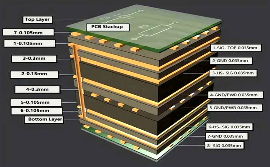
- Choose the Right Stack-Up: Design a multi-layer PCB stack-up with dedicated ground and power planes to provide a consistent reference for high-speed signals. A typical 4-layer stack-up might include signal layers on top and bottom with ground and power planes in between.
- Test and Validate: Use a Time Domain Reflectometer (TDR) during prototyping to measure impedance and identify mismatches. Adjust trace dimensions or layer spacing if deviations exceed ±10% of the target impedance.
In one automotive project, we faced signal reflections on a 5 Gbps Ethernet line due to an impedance mismatch of 15 ohms. By adjusting the trace width from 5 mils to 6.5 mils and verifying with a TDR, we brought the impedance within spec and eliminated the reflections. This step saved weeks of troubleshooting later in the design cycle.
Secret 3: Focus on EMI Reduction for Infotainment Systems
Electromagnetic interference (EMI) can wreak havoc on infotainment systems, causing noise in audio outputs, glitches in displays, or interference with nearby electronic control units (ECUs). With the tight confines of a vehicle, EMI reduction infotainment system design is non-negotiable to meet automotive EMC standards like CISPR 25.
Practical EMI Reduction Techniques:
- Implement Proper Grounding: Use a solid ground plane beneath high-speed signals to provide a low-impedance return path. Avoid splitting the ground plane under critical traces, as this can create EMI hotspots.
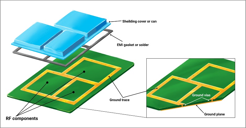
- Shield High-Speed Signals: Route sensitive traces between ground planes or add guard traces (grounded traces on either side) to shield against crosstalk and external interference.
- Add EMI Filters: Incorporate ferrite beads and bypass capacitors near power pins of ICs to filter out high-frequency noise. For example, a 0.1 μF capacitor paired with a 600-ohm ferrite bead can effectively suppress noise above 100 MHz.
- Keep Traces Away from Edges: Routing high-speed traces near the PCB edge can radiate EMI. Maintain a clearance of at least 20 mils from the board edge to minimize this risk.
During a project for an infotainment audio system, we noticed static noise in the output during testing. The root cause was EMI from a nearby switching regulator. By adding a ferrite bead filter and rerouting the audio traces away from the regulator, we reduced the noise floor by 30 dB, ensuring clear audio playback.
Secret 4: Optimize Power Delivery for High-Speed Performance
A stable power supply is essential for high-speed components in infotainment systems, such as processors and display drivers. Voltage drops or noise on power lines can degrade performance and introduce jitter in high-speed signals.
Tips for Power Delivery Network (PDN) Design:
- Use Decoupling Capacitors: Place decoupling capacitors (e.g., 0.01 μF and 0.1 μF) close to IC power pins to filter high-frequency noise. Ensure the loop inductance is minimized by placing vias directly under the capacitor pads.
- Design Wide Power Traces: Use wider traces or planes for power delivery to reduce resistance and inductance. For a 3.3V rail supplying 2A, a trace width of at least 20 mils is recommended to handle the current without significant voltage drop.
- Simulate PDN Impedance: Use tools like Cadence Sigrity to simulate the PDN and ensure the impedance remains below 1 ohm across the operating frequency range (e.g., 1 kHz to 100 MHz).
In a recent infotainment project, we encountered random reboots in a high-speed processor due to voltage dips during peak load. By adding a 10 μF bulk capacitor near the processor and optimizing the power plane layout, we stabilized the supply voltage within 50 mV of the target, resolving the issue.
Secret 5: Manage Thermal Challenges in Compact Designs
Infotainment systems often pack high-speed components into tight spaces, leading to heat buildup that can degrade performance or damage components. Effective thermal management is crucial for reliability.
Thermal Management Strategies:
- Use Thermal Vias: Place thermal vias under high-power components like processors to transfer heat to a ground plane or heat sink. A grid of 4x4 vias with a 0.3 mm diameter can significantly improve heat dissipation.
- Optimize Component Placement: Avoid clustering heat-generating components together. Spread them across the board to distribute heat evenly.
- Select Appropriate Materials: Choose PCB substrates with higher thermal conductivity, such as FR-4 with a Tg (glass transition temperature) of 170°C, for better heat tolerance in automotive environments.
Secret 6: Leverage Simulation Tools for Design Validation
Simulation is a powerful ally in high-speed PCB design, allowing engineers to identify and fix issues before fabrication. For infotainment systems, where redesigns are costly, simulation can save time and resources.
Simulation Tools and Techniques:
- Signal Integrity Simulation: Use tools like HyperLynx to simulate signal behavior and detect issues like crosstalk or reflections. For a 5 Gbps signal, ensure the eye diagram shows a clear opening with minimal jitter (e.g., less than 10 ps).
- EMI Simulation: Tools like ANSYS SIwave can predict EMI hotspots and help optimize grounding and shielding strategies before testing.
- Thermal Simulation: Perform thermal analysis with tools like FloTHERM to ensure temperatures remain within safe limits (e.g., below 85°C for most ICs) under worst-case conditions.
On a recent project, a pre-fabrication signal integrity simulation revealed potential crosstalk between two high-speed traces spaced only 5 mils apart. By increasing the spacing to 10 mils and adding a guard trace, we avoided a costly board respin after the fact.
Conclusion: Building Reliable Infotainment Systems with High-Speed PCB Design
Designing high-speed PCBs for automotive infotainment systems is a complex but rewarding challenge. By focusing on signal integrity infotainment PCB design, mastering impedance control PCB design, and implementing EMI reduction infotainment system strategies, you can create reliable, high-performance systems that meet the demands of modern vehicles. Remember to leverage simulation tools, prioritize thermal management, and follow best practices for power delivery to ensure success.
As an electrical engineer, your goal is to balance performance with practicality. Start with a solid design foundation, test rigorously, and iterate based on real-world feedback.