 ALLPCB


When it comes to designing flexible printed circuit boards (Flex PCBs), choosing the right connectors is a critical step that can make or break your project. For engineers and designers searching for flex PCB connectors, interconnect solutions for flexible circuits, or specifics like ZIF connectors for flex PCBs, understanding Design for Manufacturing (DFM) considerations is key to ensuring reliability and performance. In this comprehensive guide, we’ll explore the essential factors for selecting connectors, focusing on manufacturability, reliability, and practical tips for implementation, including soldering flex PCB connectors and ensuring the reliability of flex PCB connections.
Why Connector Choice Matters in Flex PCB Design
Flex PCBs are widely used in industries like consumer electronics, automotive, medical devices, and aerospace due to their ability to bend and conform to tight spaces. However, their unique properties—thin substrates, dynamic bending, and lightweight construction—pose challenges when selecting interconnect solutions. The right connector not only ensures a secure electrical connection but also withstands mechanical stress and environmental factors.
DFM considerations play a vital role here. A poorly chosen connector can lead to assembly issues, signal loss, or premature failure, costing time and resources. By prioritizing DFM, you can streamline production, reduce errors, and enhance the overall reliability of flex PCB connections.
Key Types of Flex PCB Connectors
Before diving into DFM considerations, let’s look at the common types of flex PCB connectors and their applications in interconnect solutions for flexible circuits.
1. Zero Insertion Force (ZIF) Connectors
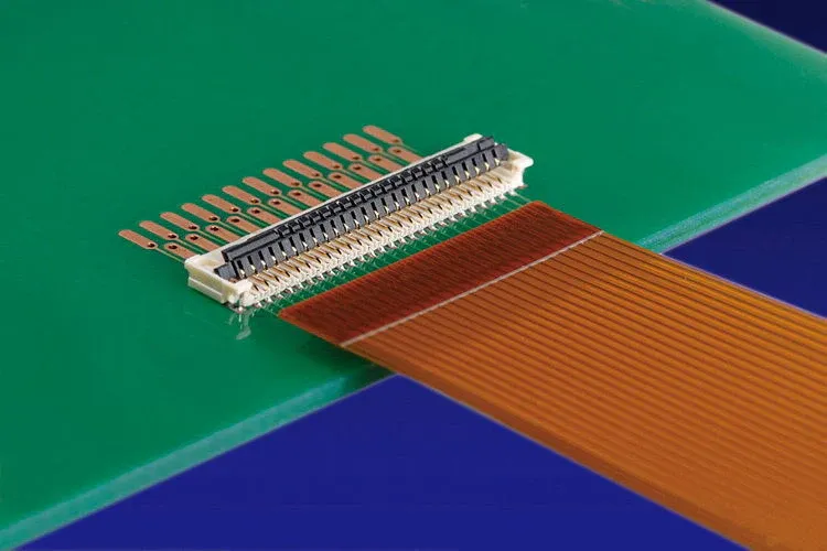
ZIF connectors for flex PCBs are popular due to their ease of use and reliability. These connectors allow the flex circuit to be inserted without force, reducing the risk of damage during assembly. Once inserted, a locking mechanism secures the connection. ZIF connectors are ideal for applications requiring frequent connections and disconnections, such as in testing environments or consumer devices like laptops and cameras.
Key Specs: ZIF connectors often support fine pitch down to 0.3 mm and can handle current ratings up to 0.5 A per contact, making them suitable for high-density designs.
2. Board-to-Flex Connectors
These connectors link a rigid PCB to a flexible circuit, providing a stable interconnect in hybrid designs. They are common in automotive and industrial applications where space constraints demand a mix of rigid and flexible components. Board-to-flex connectors typically offer higher current capacities, often up to 3 A per contact, depending on the design.
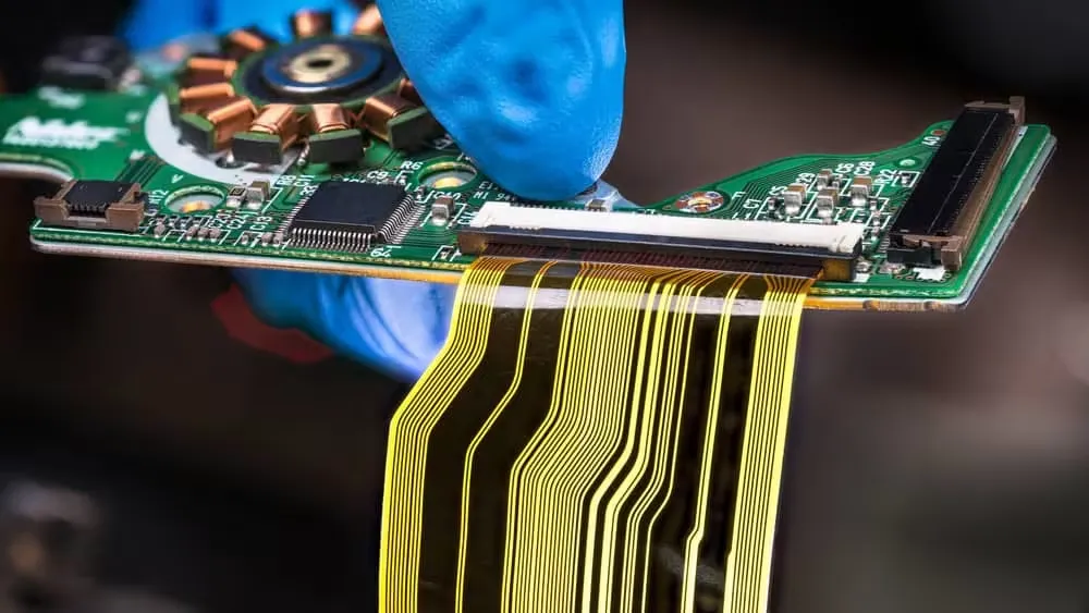
3. Flat Flexible Cable (FFC) Connectors
FFC connectors are lightweight and cost-effective, often used with flat flexible cables that integrate with Flex PCBs. They are widely used in compact electronics due to their low profile and ability to handle pitches as small as 0.5 mm.
DFM Considerations for Flex PCB Interconnects
Designing for manufacturability ensures that your Flex PCB interconnects are easy to assemble, reliable in operation, and cost-effective to produce. Below are the critical DFM factors to consider when choosing and implementing flex PCB connectors.
1. Connector Placement and Layout
The placement of connectors on a Flex PCB impacts both assembly and performance. Position connectors away from high-stress bending areas to prevent mechanical failure. For dynamic flex applications, where the circuit bends repeatedly, ensure the connector is aligned with the neutral axis of the flex to minimize strain.
Tip: Use simulation tools to analyze bending stress. Aim for a bend radius of at least 10 times the thickness of the Flex PCB (e.g., a 0.1 mm thick PCB should have a minimum bend radius of 1 mm) to avoid cracking near connectors.
2. Pitch and Pin Count Compatibility
Matching the pitch and pin count of the connector to the Flex PCB’s design is crucial for signal integrity and assembly ease. For high-density designs, opt for connectors with fine pitch (e.g., 0.3 mm or 0.5 mm) to save space. However, finer pitches can complicate soldering and increase the risk of misalignment during assembly. Balance density with manufacturability by selecting a pitch that aligns with standard assembly equipment capabilities.
3. Material and Thickness Considerations
Flex PCBs are typically made from polyimide or polyester substrates with thicknesses ranging from 0.05 mm to 0.2 mm. The connector must be compatible with these thin materials to avoid stress concentration. For instance, ZIF connectors are designed to grip thin flex circuits without excessive force, preserving the material’s integrity.
Data Point: A typical polyimide Flex PCB has a tensile strength of around 165 MPa, but improper connector selection or assembly can reduce this by introducing stress points.
4. Soldering Challenges with Flex PCB Connectors
Soldering flex PCB connectors requires precision due to the delicate nature of flexible substrates. Overheating can damage the thin copper traces or warp the material, while insufficient heat may lead to weak joints. Use low-temperature soldering techniques and ensure proper thermal management during the process.
Best Practice: Employ a soldering iron with a temperature range of 260-300°C for Flex PCBs, and limit exposure time to under 3 seconds per joint to prevent thermal damage. Additionally, consider using connectors with pre-tinned contacts to simplify the soldering process.
5. Mechanical Stress and Strain Relief
Flex PCBs often undergo bending or twisting in their final application, which can strain connector joints. Incorporate strain relief features, such as stiffeners or adhesive backing near the connector area, to distribute stress evenly. Stiffeners, typically made of FR4 or polyimide, can increase the thickness to 0.3-0.5 mm at the connection point, providing added durability.
Reliability of Flex PCB Connections
The reliability of flex PCB connections is paramount, especially in critical applications like medical devices or automotive systems. Here’s how to ensure long-term performance when selecting and designing interconnects.
1. Environmental Durability
Flex PCB connectors must withstand temperature fluctuations, humidity, and vibration. For instance, in automotive applications, connectors may be exposed to temperatures ranging from -40°C to 85°C. Choose connectors with robust housing materials (e.g., high-temperature plastics) and gold-plated contacts to resist corrosion and maintain signal integrity.
Data Point: Gold plating on contacts can reduce contact resistance to below 20 mΩ, ensuring stable performance over thousands of mating cycles.
2. Signal Integrity in High-Speed Applications
In high-speed designs, such as data transmission in telecommunications, signal integrity is a concern. Mismatched impedance or crosstalk can degrade performance. Select connectors with controlled impedance (typically around 50 Ω for single-ended signals) and low insertion loss (e.g., less than 0.5 dB at 5 GHz) to maintain signal quality.
3. Mating Cycles and Wear Resistance
For applications requiring frequent connections, like testing jigs, consider the connector’s mating cycle rating. ZIF connectors, for example, often support 20-50 mating cycles without significant wear, while some high-end options can handle up to 100 cycles. Evaluate the expected usage to choose a connector that matches durability needs.
Choosing the Right Interconnect Solution for Your Flex PCB
Selecting the best interconnect solutions for flexible circuits involves balancing performance, cost, and manufacturability. Here’s a step-by-step approach to guide your decision:
- Define Application Requirements: Determine the electrical (current, voltage, signal speed) and mechanical (bending, mating cycles) needs of your project.
- Evaluate Connector Types: Compare options like ZIF, FFC, or board-to-flex connectors based on space constraints and assembly ease.
- Assess DFM Factors: Ensure the connector aligns with manufacturing capabilities, such as soldering processes and material compatibility.
- Test for Reliability: Prototype and test the design under real-world conditions to verify the reliability of flex PCB connections.
Common Challenges and Solutions in Flex PCB Connector Design
Even with careful planning, challenges can arise when integrating connectors into Flex PCBs. Here are some common issues and how to address them:
1. Misalignment During Assembly
Misalignment can lead to poor connections or damaged traces. Use alignment features on connectors, such as guiding pins or notches, and design corresponding features on the PCB layout to ensure precise placement.
2. Thermal Stress from Soldering
As mentioned earlier, soldering flex PCB connectors can introduce thermal stress. Mitigate this by using heat sinks or thermal pads during soldering to dissipate heat quickly.
3. Connector Size vs. Space Constraints
In compact designs, large connectors can be problematic. Opt for low-profile or micro connectors with heights as low as 1 mm to fit tight spaces without compromising performance.
Partnering with Experts for Flex PCB Success
Navigating the complexities of Flex PCB interconnects doesn’t have to be a solo journey. Working with a trusted manufacturing partner can simplify the process, from connector selection to final assembly. At ALLPCB, we provide comprehensive support for Flex PCB projects, ensuring that DFM considerations are integrated into every step. Our expertise helps you achieve reliable, high-performance designs tailored to your specific needs.
Conclusion
Choosing the right flex PCB connectors and interconnect solutions for flexible circuits is a critical aspect of successful design. By focusing on DFM considerations—such as connector placement, material compatibility, soldering techniques, and reliability factors—you can create robust and efficient Flex PCB systems. Whether you’re using ZIF connectors for flex PCBs or tackling challenges like soldering flex PCB connectors, a thoughtful approach ensures the reliability of flex PCB connections in any application.
With the insights provided in this guide, you’re equipped to make informed decisions that enhance both manufacturability and performance. Keep these principles in mind as you design your next Flex PCB project, and leverage expert support to bring your ideas to life.


