 ALLPCB


Designing printed circuit boards (PCBs) for Advanced Driver Assistance Systems (ADAS) requires precision, reliability, and the right tools to meet the stringent demands of automotive applications. If you’re searching for the best ADAS PCB design software or automotive PCB layout tools, you’re in the right place. This guide will help you understand the key features to look for in PCB design software, focusing on aspects like high-speed design, signal integrity, and thermal management. We'll dive deep into why these features matter for ADAS and how they can impact your project’s success.
In this comprehensive blog, we’ll explore the unique challenges of designing PCBs for ADAS, break down essential software capabilities, and provide actionable insights to help you choose the right tools for your automotive projects. Whether you're an engineer working on radar systems, camera modules, or sensor integration, this post will guide you through the process with clarity and depth.
Why ADAS Applications Demand Specialized PCB Design Software
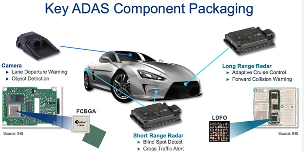
ADAS technologies, such as adaptive cruise control, lane departure warnings, and automatic emergency braking, rely heavily on complex electronics packed into tight spaces. These systems process data in real-time, often handling high-speed signals from sensors like LiDAR, radar, and cameras. A single glitch or delay can compromise safety, making PCB design a critical factor in automotive innovation.
Unlike standard PCB projects, ADAS designs must withstand harsh conditions like temperature fluctuations, vibrations, and electromagnetic interference (EMI). This is why using specialized ADAS PCB design software and automotive PCB layout tools is non-negotiable. These tools help ensure signal integrity, manage heat dissipation, and optimize layouts for reliability under extreme conditions.
Key Challenges in PCB Design for ADAS Applications
Before diving into software features, let’s look at the unique challenges of designing PCBs for ADAS. Understanding these hurdles will help you prioritize the right tools for your needs.
- High-Speed Data Processing: ADAS systems often operate at frequencies above 1 GHz for radar and LiDAR signals. Any mismatch in impedance (typically targeted at 50 ohms for high-speed lines) can cause signal degradation.
- Compact Layouts: With space at a premium in vehicles, PCBs must fit into small enclosures while maintaining functionality, requiring precise routing and layer stacking.
- Thermal Management: Components like processors and power regulators generate significant heat, often exceeding 85°C in automotive environments, which can affect performance if not managed properly.
- Signal Integrity and EMI: High-speed signals are prone to crosstalk and noise, especially in densely packed boards, necessitating careful design to minimize interference.
- Regulatory Compliance: Automotive PCBs must meet strict standards like ISO 26262 for functional safety, requiring tools that support documentation and validation.
Given these challenges, selecting the right high-speed PCB design software and supporting tools becomes a critical decision for engineers working on ADAS projects.
Essential Features to Look for in ADAS PCB Design Software
Choosing the right software involves evaluating several key features that directly impact the quality and reliability of your ADAS designs. Here’s a detailed breakdown of what to prioritize when selecting automotive PCB layout tools.
1. Support for High-Speed PCB Design
High-speed signals are the backbone of ADAS systems, with data rates often exceeding 5 Gbps for applications like camera feeds or sensor data. Software with dedicated high-speed PCB design capabilities ensures that traces are routed with controlled impedance, minimizing reflections and signal loss. Look for tools that allow you to define specific rules for trace width, spacing, and via placement to maintain signal quality.
For instance, a typical differential pair for high-speed signals might require a trace width of 5 mils and spacing of 8 mils to achieve a 100-ohm differential impedance. The right software will automatically check these parameters during the design phase, saving time and reducing errors.
2. Signal Integrity Simulation Tools
Ensuring signal quality is paramount in ADAS, where even a small delay or distortion can lead to system failures. Signal integrity simulation tools allow you to analyze potential issues like crosstalk, jitter, and signal loss before fabrication. These tools simulate how signals behave under real-world conditions, helping you identify and fix problems early.
For example, simulation might reveal that a 2 GHz signal experiences a 3 dB loss over a 10-inch trace, prompting you to adjust the layout or add repeaters. Software with built-in simulation capabilities can model these scenarios, providing insights into eye diagrams and timing margins to ensure reliable performance.
3. Thermal Analysis Software for PCBs
Heat management is a major concern in automotive electronics, where ambient temperatures can range from -40°C to 105°C. Thermal analysis software for PCBs helps predict how heat dissipates across your board, identifying hotspots that could degrade components or cause failures.
Advanced tools can simulate thermal profiles based on power dissipation values (e.g., a processor dissipating 5W of heat) and material properties like copper thickness (typically 1 oz/ft2 for standard layers). This allows you to place heat sinks, vias, or ventilation strategically to keep temperatures within safe limits, such as below 85°C for critical components.
4. Advanced Routing and Layout Capabilities
ADAS PCBs often require multilayer designs with 8 or more layers to accommodate complex circuits in a compact form factor. Automotive PCB layout tools should offer intuitive routing options, including automated and manual modes, to handle dense layouts without compromising signal paths.
Look for software that supports blind and buried vias, as well as HDI (High-Density Interconnect) technology, which is common in automotive designs. These features help reduce board size while maintaining connectivity, crucial for fitting electronics into tight vehicle spaces.
5. EMI and Noise Mitigation Features
Electromagnetic interference can disrupt ADAS functionality, especially with high-speed signals and multiple components in close proximity. Good PCB design software includes features to minimize EMI, such as ground plane optimization, shielding options, and rules for loop area reduction.
For example, ensuring a continuous ground plane beneath high-speed traces can reduce noise by up to 20 dB, significantly improving system reliability. Software that flags potential EMI issues during design can save hours of troubleshooting later.
6. Integration with Mechanical Design Tools
In automotive applications, PCBs must fit precisely within enclosures and align with other mechanical components. Software that integrates with mechanical design platforms allows you to import 3D models of enclosures and verify clearances, ensuring your PCB fits perfectly without interference.
This is especially important for ADAS modules mounted near engines or in tight dashboard spaces, where even a 1 mm misalignment can cause assembly issues.

7. Compliance and Documentation Support
Automotive projects must adhere to strict standards for safety and reliability. PCB design software should offer features to document your design process, generate bills of materials (BOMs), and support compliance with standards like ISO 26262. This ensures traceability and simplifies audits or certifications.
How to Evaluate PCB Design Software for Your ADAS Project
With so many tools available, narrowing down your options can feel overwhelming. Here’s a step-by-step approach to evaluate ADAS PCB design software based on your specific needs.
- Define Project Requirements: List the key specifications of your ADAS project, such as signal speeds (e.g., 2.5 Gbps for camera data), layer count, and thermal constraints. This will help you focus on software that meets these needs.
- Test High-Speed Features: Request demos or trial versions to test high-speed PCB design software capabilities. Check if the tool supports impedance control and differential pair routing out of the box.
- Assess Simulation Tools: Ensure the software includes signal integrity simulation tools and thermal analysis software for PCBs. Run sample simulations to see how intuitive and accurate the results are.
- Check Scalability: Choose software that can handle increasingly complex designs as ADAS technologies evolve. Look for updates or plugins that support emerging standards.
- Evaluate Support and Community: Opt for tools with strong technical support and active user communities. Access to tutorials, forums, and expert advice can be invaluable during challenging projects.
Benefits of Using the Right Software for ADAS PCB Design
Investing in the right automotive PCB layout tools offers several advantages that directly impact your project’s outcome and timeline.
- Faster Time-to-Market: Advanced features like automated routing and simulation reduce design iterations, helping you meet tight deadlines.
- Cost Savings: Identifying issues like thermal hotspots or signal loss during the design phase prevents costly rework after fabrication.
- Improved Reliability: Tools that prioritize signal integrity and EMI mitigation ensure your ADAS systems perform consistently, even in harsh conditions.
- Enhanced Safety: Reliable PCB designs contribute to the overall safety of ADAS features, protecting drivers and passengers by minimizing system failures.
Trends Shaping PCB Design Software for ADAS
The field of ADAS is evolving rapidly, and so are the tools used to design its components. Staying ahead of these trends can give you a competitive edge in automotive electronics.
- AI-Driven Design: Some modern tools use artificial intelligence to optimize layouts, predict thermal issues, and suggest routing paths, reducing manual effort.
- Cloud-Based Collaboration: Cloud platforms enable teams to work on designs simultaneously, streamlining workflows for global automotive projects.
- Focus on Miniaturization: As ADAS modules shrink, software is adapting to support finer pitch components and advanced HDI techniques.
- Enhanced Simulation: Future tools will offer even more detailed simulations, incorporating real-time environmental factors like vibration and humidity.
Conclusion: Making an Informed Choice for ADAS PCB Design
Selecting the right ADAS PCB design software is a critical step in ensuring the success of your automotive projects. By focusing on features like high-speed design support, signal integrity simulation tools, and thermal analysis software for PCBs, you can create reliable, high-performance boards that meet the demanding requirements of ADAS applications.
Take the time to evaluate your project’s specific needs, test potential tools, and prioritize software that offers scalability and robust support. With the right automotive PCB layout tools in hand, you’ll be well-equipped to tackle the challenges of designing for the future of automotive safety and innovation.
At ALLPCB, we understand the importance of precision and reliability in every stage of PCB development. Our expertise and resources are here to support your journey in creating cutting-edge ADAS solutions that drive the industry forward.


