 ALLPCB


If you're dealing with a damaged printed circuit board (PCB) and need to fix a plated through-hole (PTH), you're in the right place. Plated through-holes are critical for ensuring electrical connections between layers of a PCB, and damage to them can render a board unusable. In this comprehensive guide, we'll walk you through the PTH repair process, including using a PTH repair kit, eyelet repair for PTH, and even DIY PTH repair methods to save your board from becoming scrap. Whether you're a hobbyist or a professional, this step-by-step tutorial will help you tackle damaged PTH repair with confidence.
Below, we dive deep into the world of PTH repair, covering everything from the tools you'll need to the detailed procedures for restoring your PCB. Let’s get started!
What Are Plated Through-Holes (PTH) and Why Do They Matter?
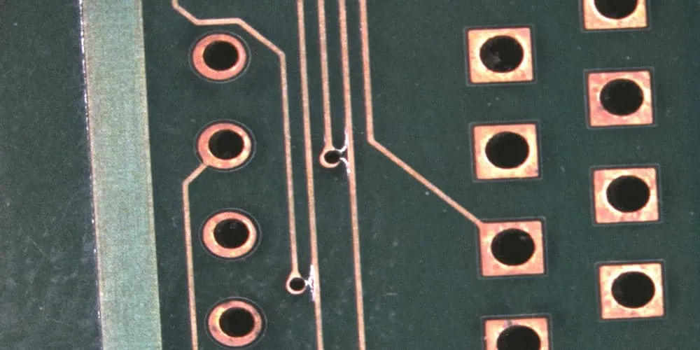
Plated through-holes are small holes drilled through a PCB that are coated with a conductive material, typically copper, to create an electrical connection between different layers of the board. These holes also serve as mounting points for through-hole components like resistors, capacitors, and connectors. PTHs are essential for maintaining signal integrity and ensuring the board functions as intended.
When a PTH becomes damaged—whether through mishandling, improper component removal, or manufacturing defects—it can disrupt the connection, leading to circuit failure. Common issues include cracked barrels (the conductive lining inside the hole), lifted pads, or completely broken connections. Repairing these damages is often more cost-effective than replacing the entire PCB, especially for complex or expensive boards.
Common Causes of Damaged PTHs
Before we dive into the PTH repair process, it’s important to understand why these damages occur. Identifying the root cause can help prevent future issues. Here are some common reasons for damaged PTH repair needs:
- Improper Component Removal: Using excessive heat or force when desoldering components can crack the PTH barrel or lift the surrounding pad.
- Mechanical Stress: Dropping a PCB or applying too much pressure during assembly can cause physical damage to the holes.
- Thermal Stress: Repeated heating and cooling cycles during soldering can weaken the PTH structure over time.
- Manufacturing Defects: Poor plating quality or insufficient copper thickness during production can lead to weak PTHs that fail under stress.
Understanding these causes can guide you in handling your PCBs more carefully during assembly or rework.
Tools and Materials Needed for PTH Repair
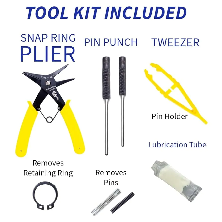
To successfully repair a damaged plated through-hole, you’ll need the right tools and materials. A well-equipped PTH repair kit is often the best starting point, as it typically includes everything necessary for the job. Here’s a breakdown of what you’ll need:
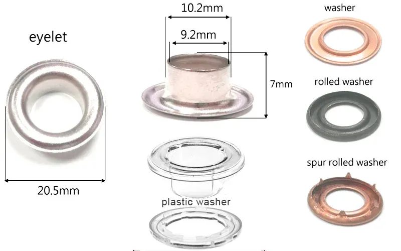
- Eyelets or Funnelets: Small copper or tin-plated tubes used to restore the conductive path in a damaged PTH. Eyelets come in various sizes to match different hole diameters.
- Drill and Drill Bits: A precision drill with micro bits (e.g., 0.5mm to 1.5mm) to clean out damaged holes or enlarge them slightly for eyelet insertion.
- Setting Tool: A specialized tool to flare or crimp the eyelet into place, ensuring a secure fit.
- Soldering Iron and Solder: A fine-tip soldering iron (around 25-40 watts) and high-quality solder for securing the eyelet and reconnecting traces.
- Desoldering Tools: A desoldering pump or wick to remove old solder from the damaged area.
- Epoxy or Adhesive: For securing eyelets or repairing surrounding board material if needed.
- Magnifying Glass or Microscope: To inspect small PTHs and ensure precision during repair.
- Cleaning Supplies: Isopropyl alcohol and a brush to clean the area after repair.
- Multimeter: To test continuity and ensure the repair restores the electrical connection.
Many of these items are included in a standard PTH repair kit, which is designed specifically for tasks like eyelet repair PTH. If you're attempting a DIY PTH repair, ensure you have these essentials on hand to avoid interruptions.
Step-by-Step PTH Repair Process
Now that you have the tools ready, let’s walk through the detailed PTH repair process. This guide focuses on using eyelets, as they are a widely accepted method for eyelet repair PTH and are suitable for both professional and DIY PTH repair projects. Follow these steps carefully to ensure a reliable fix.
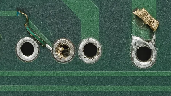
Step 1: Assess the Damage
Start by closely inspecting the damaged PTH using a magnifying glass or microscope. Look for cracks in the copper barrel, lifted pads, or broken connections to inner layers. Use a multimeter to test for continuity between the top and bottom layers of the PCB. If there’s no connection, or if the resistance is unusually high (e.g., above 0.1 ohms for a typical PTH), repair is necessary.
Step 2: Clean the Damaged Area
Remove any debris, old solder, or damaged material from the PTH. Use a desoldering pump or wick to clear out solder from the hole. If the hole is obstructed or the barrel is cracked, carefully drill out the damaged material using a micro drill bit slightly larger than the original hole (e.g., 0.8mm for a 0.6mm hole). Be cautious not to damage surrounding traces or pads. After drilling, clean the area with isopropyl alcohol to remove flux residue or dust.
Step 3: Select the Right Eyelet
Choose an eyelet from your PTH repair kit that matches the hole diameter and the board thickness. Eyelets typically come in sizes ranging from 0.5mm to 2.0mm in diameter, with flange styles like flat or funnel for different clearance needs. For example, a flat flange eyelet is ideal for low-profile repairs where components sit close to the board surface. Ensure the eyelet’s length matches the PCB thickness (e.g., 1.6mm for a standard board) to avoid protrusion issues.
Step 4: Insert and Secure the Eyelet
Insert the eyelet into the cleaned hole from the component side of the PCB. The flange should rest flat against the surface. Use a setting tool to flare or crimp the other end of the eyelet on the opposite side of the board. This secures the eyelet in place and ensures a tight mechanical connection. Apply gentle pressure to avoid damaging the board—over-crimping can crack the surrounding material.
Step 5: Solder the Eyelet
Using a fine-tip soldering iron, apply solder to both ends of the eyelet where it meets the PCB pads. Use just enough solder to form a smooth, shiny fillet without creating blobs that could interfere with component insertion. If the PTH connects to inner layers, ensure the solder flows evenly to maintain conductivity. Allow the area to cool naturally to prevent thermal stress.
Step 6: Test the Repair
After soldering, use a multimeter to test for continuity again. You should see a low resistance reading (close to 0 ohms) indicating a successful connection. If the PTH is part of a signal path, consider testing the board under operating conditions to ensure signal integrity—high-frequency signals, for instance, should maintain impedance within acceptable limits (e.g., 50 ohms for many RF applications).
Step 7: Clean and Inspect
Finally, clean the repaired area with isopropyl alcohol and a brush to remove any flux or residue. Inspect the repair under magnification to ensure there are no cold solder joints, cracks, or other defects. If everything looks good, your damaged PTH repair is complete!
DIY PTH Repair: Tips for Hobbyists
If you’re attempting a DIY PTH repair without a professional PTH repair kit, you can still achieve good results with basic tools and materials. Here are some practical tips to help you succeed:
- Use Household Items: If you don’t have eyelets, small copper wires or tubing can sometimes be used as a makeshift replacement. Strip a thin wire, insert it through the hole, and fold the ends to mimic an eyelet flange before soldering.
- Practice First: Test your repair technique on a scrap PCB before working on a valuable board. This helps you get comfortable with drilling, inserting eyelets, and soldering in tight spaces.
- Minimize Heat: Use a low-wattage soldering iron and work quickly to avoid overheating the PCB, which can delaminate layers or damage nearby components.
- Double-Check Connections: Always test with a multimeter after repair. A poor connection might work initially but fail under load or over time.
While DIY PTH repair can save money, investing in a proper PTH repair kit is recommended for consistent, reliable results, especially for critical projects.
Preventing Future PTH Damage
Repairing a damaged PTH is rewarding, but preventing damage in the first place is even better. Here are some best practices to protect your PCBs during handling and assembly:
- Use Proper Desoldering Techniques: Always use a desoldering pump or wick to remove components, and avoid excessive heat (keep soldering iron temperatures below 300°C for most boards).
- Handle with Care: Store PCBs in protective cases or antistatic bags to prevent physical damage from drops or scratches.
- Support During Assembly: Use a PCB holder or vise during soldering to avoid flexing the board, which can stress PTHs.
- Inspect Before Use: Check new boards for manufacturing defects like thin plating or misaligned holes before assembling components.
Advanced Considerations for PTH Repair
For engineers working on high-reliability or high-frequency PCBs, additional factors come into play during damaged PTH repair. For instance, the repair must maintain the board’s original impedance characteristics to avoid signal degradation. A poorly repaired PTH in an RF circuit could introduce unwanted capacitance or inductance, skewing impedance from the standard 50 ohms and causing signal reflections.
Additionally, if the PTH connects to inner layers, ensure the eyelet or repair method restores the connection without creating shorts. In such cases, using a conductive epoxy alongside the eyelet can help bridge inner-layer connections if soldering alone isn’t sufficient. Always refer to industry standards like IPC-7711/7721 for guidelines on advanced repairs, especially for mission-critical applications.
Conclusion: Save Your PCBs with Confidence
Repairing a plated through-hole doesn’t have to be intimidating. With the right tools, such as a PTH repair kit, and a clear understanding of the PTH repair process, you can restore functionality to your damaged PCBs and avoid costly replacements. Whether you’re using eyelet repair PTH techniques or exploring DIY PTH repair methods, the steps outlined in this guide will help you tackle damaged PTH repair effectively.
By following best practices and taking preventive measures, you can minimize future damage and keep your projects on track. Remember, precision and patience are key to a successful repair. So, gather your tools, inspect your board, and start saving your PCBs today!


