 ALLPCB


Are you a hobbyist looking to build your own Engine Control Unit (ECU) PCB for managing an engine? A DIY ECU PCB project can be an exciting and rewarding challenge, allowing you to customize engine performance with tools like Arduino and open-source engine control systems. In this comprehensive guide, we’ll walk you through the essentials of designing and building your own ECU PCB, tailored for hobbyist engine management. Whether you're tuning a car, motorcycle, or a custom project, this step-by-step tutorial will help you get started with confidence.
What Is a DIY ECU PCB and Why Build One?
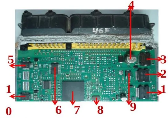
An Engine Control Unit (ECU) is the brain of a vehicle’s engine system, controlling critical functions like fuel injection, ignition timing, and air intake. A DIY ECU PCB project involves creating a custom circuit board to perform these tasks, often using affordable microcontrollers like Arduino and open-source engine control software. Building your own ECU PCB offers several benefits: cost savings, full customization, and a deeper understanding of engine management systems.
For hobbyists, this project is a perfect blend of electronics and automotive passion. By using open-source tools and platforms, you can avoid the high costs of commercial ECUs while tailoring the system to your specific needs. Let’s dive into the details of how to build your own ECU PCB and bring your engine management ideas to life.
Understanding the Basics of Engine Control Units
Before starting your DIY ECU PCB project, it’s important to grasp the core functions of an ECU. The unit processes data from various sensors, such as the crankshaft position sensor, throttle position sensor, and oxygen sensor, to make real-time decisions. For example, it adjusts the fuel injector pulse width (often measured in milliseconds, e.g., 2-10 ms) to maintain an optimal air-fuel ratio, typically around 14.7:1 for gasoline engines.
A typical ECU manages:
- Fuel Injection: Controls the amount of fuel delivered to the engine based on sensor inputs.
- Ignition Timing: Determines the exact moment the spark plug fires, often within 1-2 degrees of crankshaft rotation accuracy.
- Idle Speed: Maintains a stable idle, usually between 600-800 RPM for most cars.
- Emissions Control: Adjusts parameters to minimize harmful emissions.
For a hobbyist engine management system, your DIY ECU PCB will need to interface with these sensors and actuators, process data quickly (often at speeds of 100-200 Hz for real-time updates), and execute commands reliably.
Tools and Components for Your Arduino ECU Project
Building your own ECU PCB starts with gathering the right tools and components. Since this is a hobbyist project, we’ll focus on using an Arduino as the core microcontroller due to its affordability, ease of use, and strong community support for open-source engine control.
Essential Components
- Microcontroller: An Arduino board (e.g., Arduino Mega or Uno) with enough processing power (16 MHz clock speed for Uno) and input/output pins (at least 20 for complex setups).
- Sensors: Crankshaft position sensor, throttle position sensor, MAP (Manifold Absolute Pressure) sensor for pressure readings (typically 0-5V output), and temperature sensors.
- Actuators: Fuel injectors and ignition coils with compatible drivers (e.g., MOSFETs to handle currents up to 10A for injectors).
- Power Supply: A stable 5V or 12V supply with current capacity of at least 2A to power the board and components.
- PCB Materials: Copper-clad board or pre-designed PCB layout, soldering equipment, and connectors for wiring harnesses.
- Communication Modules: CAN bus module (e.g., MCP2515) for vehicle communication at speeds up to 1 Mbps if integrating with modern systems.
Software Tools
- Open-Source Engine Control Software: Platforms like Speeduino, a popular firmware for Arduino-based ECUs, provide pre-built code for fuel and ignition mapping.
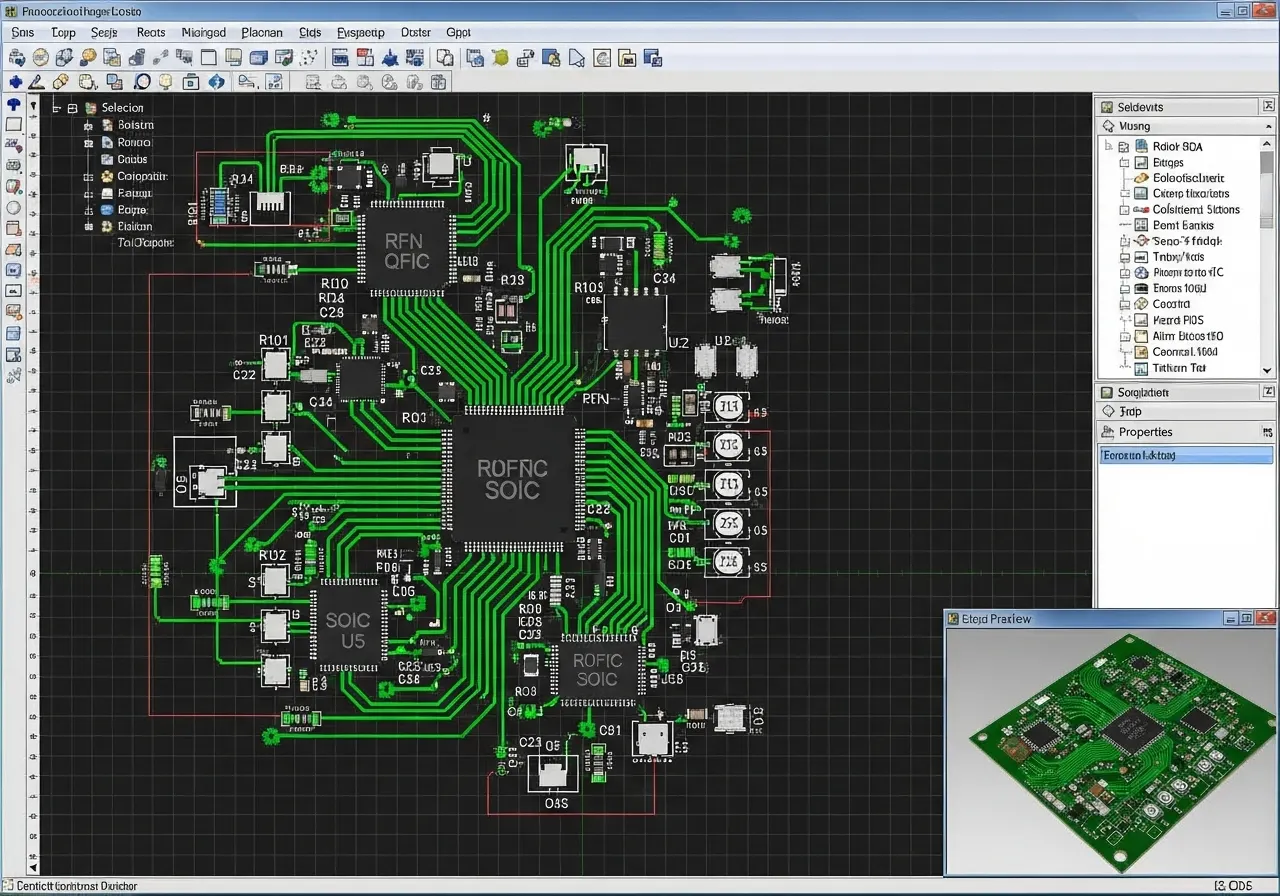
- PCB Design Software: Use free tools like KiCad to design your custom ECU PCB layout with proper trace widths (e.g., 0.5mm for signal traces, 2mm for power).
- Programming Environment: Arduino IDE for coding and uploading firmware to your board.
Step-by-Step Guide to Build Your Own ECU PCB
Now that you have your tools and components, let’s walk through the process of designing and building your DIY ECU PCB. This guide assumes basic electronics knowledge, such as soldering and reading schematics.
Step 1: Define Your Project Requirements
Start by outlining what your ECU needs to control. For a basic hobbyist engine management system, focus on fuel injection and ignition timing for a single-cylinder or small engine. List the sensors and actuators you’ll use, and ensure your Arduino has enough pins (e.g., 14 digital I/O pins for a basic setup).
Step 2: Design the Schematic
Using PCB design software, create a schematic that connects your Arduino to the necessary components. Include:
- Analog inputs for sensors (e.g., 0-5V signals from throttle position sensor).
- Digital outputs for controlling injectors and ignition via transistors or MOSFETs.
- Power regulation circuits to handle 12V vehicle voltage down to 5V for the Arduino (use a regulator like LM7805 with a 1A rating).
Ensure proper grounding to avoid noise interference, which can affect sensor readings by up to 0.1V, leading to inaccurate data.
Related Reading: ECU PCB Design: Minimizing EMI for Automotive Reliability
Step 3: Layout the PCB
Translate your schematic into a PCB layout. Keep high-current traces (e.g., for injectors) short and wide (at least 2mm) to handle currents of 5-10A. Place sensitive analog components away from noisy digital signals to maintain signal integrity. Aim for a board size of around 100mm x 80mm for a compact design that fits in an enclosure.
Step 4: Fabricate the PCB
Once your design is ready, you can either etch your own PCB at home using a copper-clad board and ferric chloride or order a professionally manufactured board. Ensure the board supports through-hole components if you’re soldering by hand, as they’re easier for hobbyists to work with compared to surface-mount devices.
Step 5: Assemble and Solder Components
Solder all components onto the PCB, starting with low-profile parts like resistors and moving to larger components like connectors. Double-check polarity for capacitors and diodes to avoid damage. Use a multimeter to test continuity and ensure no short circuits exist, especially on power traces handling 12V.
Step 6: Program the Arduino for Engine Control
Download an open-source engine control firmware like Speeduino, which supports Arduino boards for hobbyist engine management. Upload the firmware using the Arduino IDE, and configure settings like injector pulse width (e.g., 2ms at idle) and ignition advance (e.g., 10 degrees before top dead center at 1000 RPM). Use a tuning interface to adjust these parameters based on real engine data.
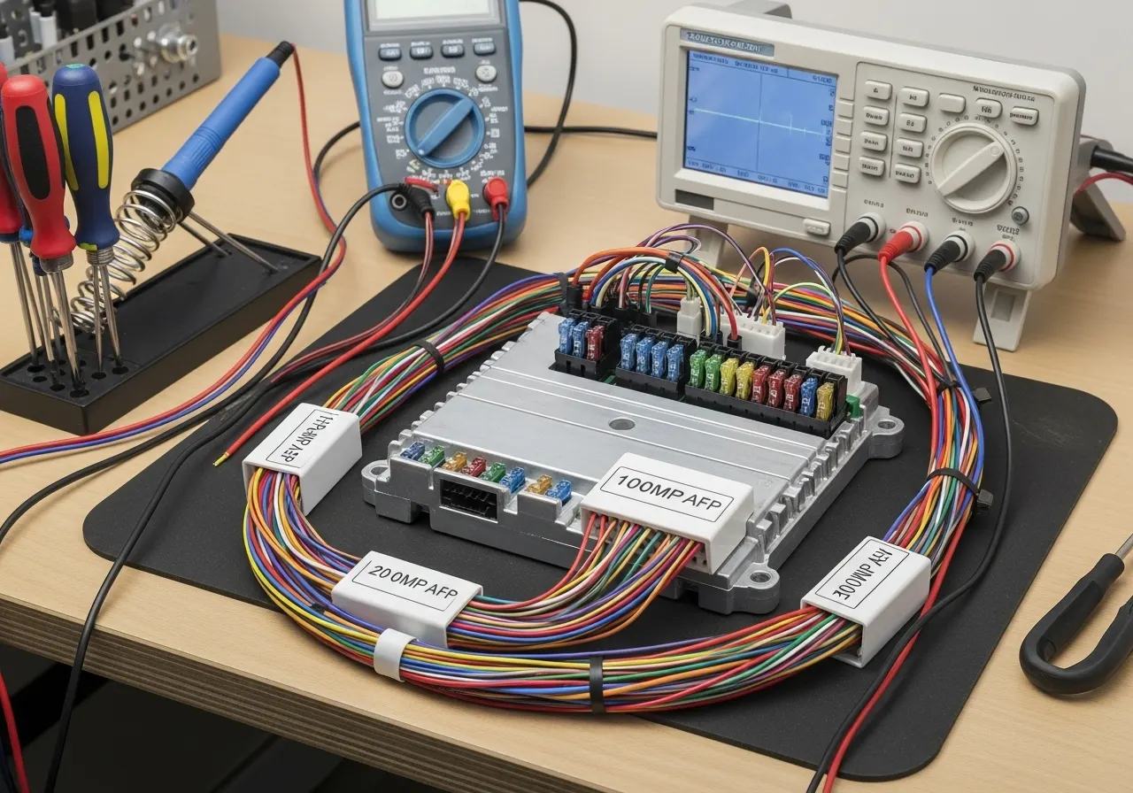
Step 7: Test and Debug
Connect your DIY ECU PCB to a test engine or simulator setup. Verify sensor readings (e.g., MAP sensor should read around 100 kPa at sea level with the engine off) and actuator responses (e.g., injector clicks when triggered). Use a logic analyzer to check signal timing if issues arise, ensuring pulses are within 1ms of expected values.
Challenges in Hobbyist Engine Management Projects
While building your own ECU PCB is rewarding, it comes with challenges. Here are a few common hurdles and how to overcome them:
- Signal Noise: Engine environments are noisy, with electromagnetic interference affecting sensor signals. Use shielded cables and add capacitors (e.g., 0.1μF) near sensor inputs to filter noise.
- Heat and Vibration: Engines generate heat (up to 100°C) and vibration. Mount your PCB in a protective enclosure and use heat-resistant components rated for at least 125°C.
- Processing Speed: An Arduino operates at 16 MHz, which may struggle with complex multi-cylinder engines. For advanced projects, consider faster microcontrollers like the STM32 series with clock speeds up to 72 MHz.
Related Reading: Essential Tools for ECU PCB Repair: A DIY Guide
Safety Considerations for DIY ECU Projects
Working with engine electronics involves risks. Always follow these safety tips:
- Disconnect the vehicle battery before wiring to prevent shorts, as 12V systems can deliver over 100A in a fault condition.
- Test your ECU on a bench setup before installing it in a running engine to avoid damage from incorrect outputs.
- Use fuses (e.g., 5A rating) on power lines to protect against overcurrent.
Expanding Your Arduino ECU Capabilities
Once your basic DIY ECU PCB is functional, you can enhance it with additional features:
- Data Logging: Add an SD card module to log engine data (e.g., RPM, fuel usage) at 10 Hz for analysis.
- Bluetooth Monitoring: Integrate a Bluetooth module (e.g., HC-05) for real-time monitoring on a smartphone at baud rates of 9600.
- Advanced Tuning: Use open-source tuning software to create custom fuel maps, adjusting injector timing by 0.1ms increments for precision.
Why Choose Open-Source Engine Control?
Open-source engine control systems are a game-changer for hobbyists. They provide free access to community-developed firmware and tuning tools, saving you from expensive proprietary systems that can cost over $1000. With platforms like Speeduino, you get regular updates and support from a global community of DIY enthusiasts, ensuring your Arduino ECU stays relevant and adaptable.
Conclusion: Start Your DIY ECU PCB Journey Today
Building your own ECU PCB is a fantastic way to dive into hobbyist engine management. With an Arduino, open-source engine control software, and a custom-designed PCB, you can create a tailored solution for your engine project. From designing the circuit to programming and testing, each step teaches valuable skills in electronics and automotive systems.
By following this guide, you now have the foundation to start your DIY ECU PCB project. Take it slow, test thoroughly, and enjoy the process of bringing your engine control ideas to life. Whether it’s for a go-kart, motorcycle, or vintage car, your custom ECU will give you full control over performance and efficiency.


