 ALLPCB


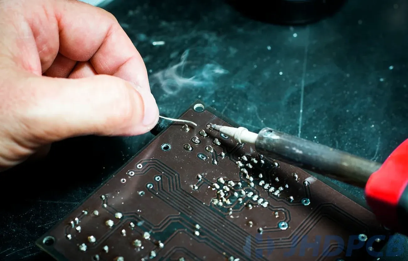
If you're new to working with electronic control unit (ECU) printed circuit boards (PCBs), soldering components might seem intimidating. But with the right tools, techniques, and safety practices, you can master the art of soldering ECU PCB components. This guide is designed for beginners, covering everything from the basics of soldering to specific methods like SMD soldering for beginners and through-hole soldering techniques. We'll also dive into soldering safety and best soldering practices for PCBs to ensure your work is reliable and professional.
Whether you're repairing an automotive ECU or building one from scratch, this detailed guide will walk you through each step. Let's get started on your journey to becoming a confident soldering technician.
What Is an ECU PCB and Why Is Soldering Important?
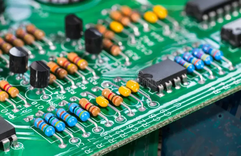
An ECU PCB is the brain of many automotive systems, controlling functions like engine performance, transmission, and emissions. These boards are packed with tiny components that need to be soldered precisely to ensure proper electrical connections and functionality. Soldering is the process of joining metal surfaces using a molten metal alloy, known as solder, to create a strong and conductive bond.
Proper soldering is critical for an ECU PCB because a single bad connection can cause system failures, leading to issues like engine misfires or complete shutdowns. For beginners, learning to solder these components correctly is the foundation of working with automotive electronics.
Essential Tools and Materials for Soldering ECU PCB Components
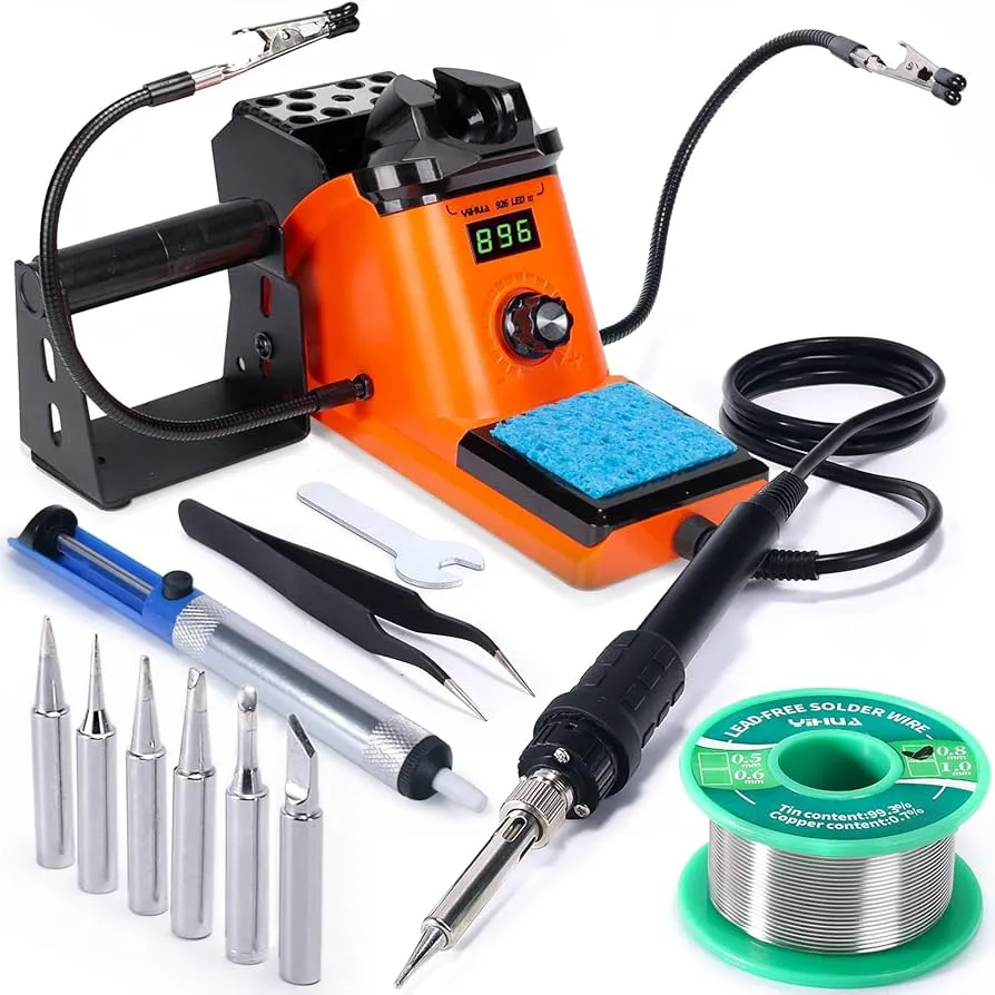
Before you begin soldering, gather the right tools and materials. Using quality equipment will make the process smoother and safer. Here's what you'll need:
- Soldering Iron: Choose a temperature-controlled soldering iron with a fine tip (1mm or smaller) for precision on small ECU components. A 25-40 watt iron is ideal for most PCB work.
- Solder: Use lead-free rosin-core solder with a diameter of 0.5mm to 0.8mm for fine work on PCBs.
- Flux: Flux helps the solder flow and bond to the metal surfaces, improving connection quality.
- Desoldering Tools: A desoldering pump or wick is useful for removing old solder or fixing mistakes.
- Tweezers: Precision tweezers help place small components, especially for surface-mount device (SMD) soldering.
- Magnifying Glass or Microscope: ECU components are tiny, often requiring magnification for accurate placement and inspection.
- Workbench Setup: A clean, well-lit workspace with an anti-static mat to protect sensitive components from electrostatic discharge (ESD).
- Safety Gear: Safety glasses and a ventilated area or fume extractor to avoid inhaling solder fumes.
Having these tools ready will set you up for success when soldering ECU PCB components, whether you're working with through-hole or SMD parts.
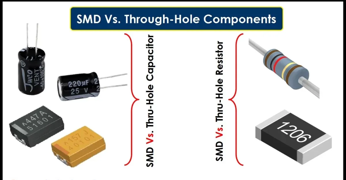
Understanding the Basics: Through-Hole vs. SMD Soldering
ECU PCBs often contain two types of components: through-hole and surface-mount devices (SMD). Each type requires a different soldering approach, so let's break them down for beginners.
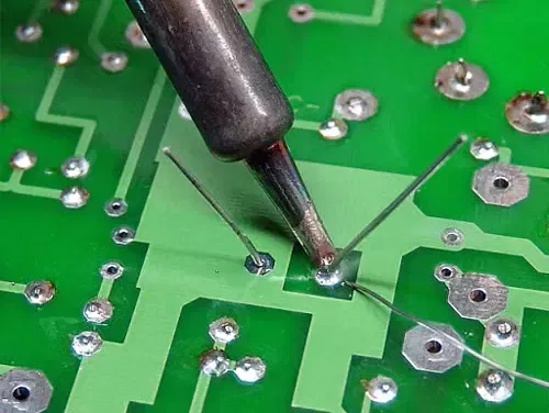
Through-Hole Soldering Techniques
Through-hole components have leads (metal pins) that pass through holes in the PCB and are soldered on the opposite side. This method is often easier for beginners due to the larger size of components and leads. Here's a step-by-step guide to through-hole soldering techniques:
- Insert the Component: Place the component leads through the designated holes on the PCB. Ensure the component sits flush against the board.
- Heat the Joint: Set your soldering iron to around 300°C (572°F). Place the tip on the pad and lead simultaneously for 2-3 seconds to heat them evenly.
- Apply Solder: Touch the solder to the heated joint (not the iron tip). The solder should melt and flow around the lead, forming a shiny, cone-shaped joint. Use about 1-2mm of solder per joint.
- Remove the Iron: Take the soldering iron away and let the joint cool for a few seconds. Avoid moving the component during cooling to prevent a cold solder joint.
- Trim Excess Leads: Use wire cutters to trim the excess lead close to the solder joint.
Through-hole soldering is common for larger components on ECU PCBs, such as connectors or capacitors, and provides a strong mechanical bond.
SMD Soldering for Beginners
Surface-mount devices are smaller and sit directly on the surface of the PCB, with pads instead of leads. SMD soldering for beginners can be tricky due to the small size, but with practice, it becomes manageable. Follow these steps:
- Prepare the Pads: Apply a thin layer of flux to the PCB pads to help the solder flow and prevent oxidation.
- Place the Component: Use tweezers to position the SMD component on the pads, aligning it precisely with the markings on the PCB.
- Heat and Solder One Side: Set your soldering iron to 280-300°C (536-572°F). Apply a small amount of solder to one pad, then place the component pin on it while reheating the solder to secure it.
- Solder Remaining Pins: Add solder to the remaining pins, ensuring each connection is shiny and free of excess solder. Avoid bridging (connecting adjacent pins with solder).
- Inspect the Joints: Use a magnifying glass to check for cold joints or bridges. If needed, use a desoldering wick to remove excess solder.
SMD components, like microcontrollers and resistors, are common in modern ECU designs due to their compact size, but they require a steady hand and patience.
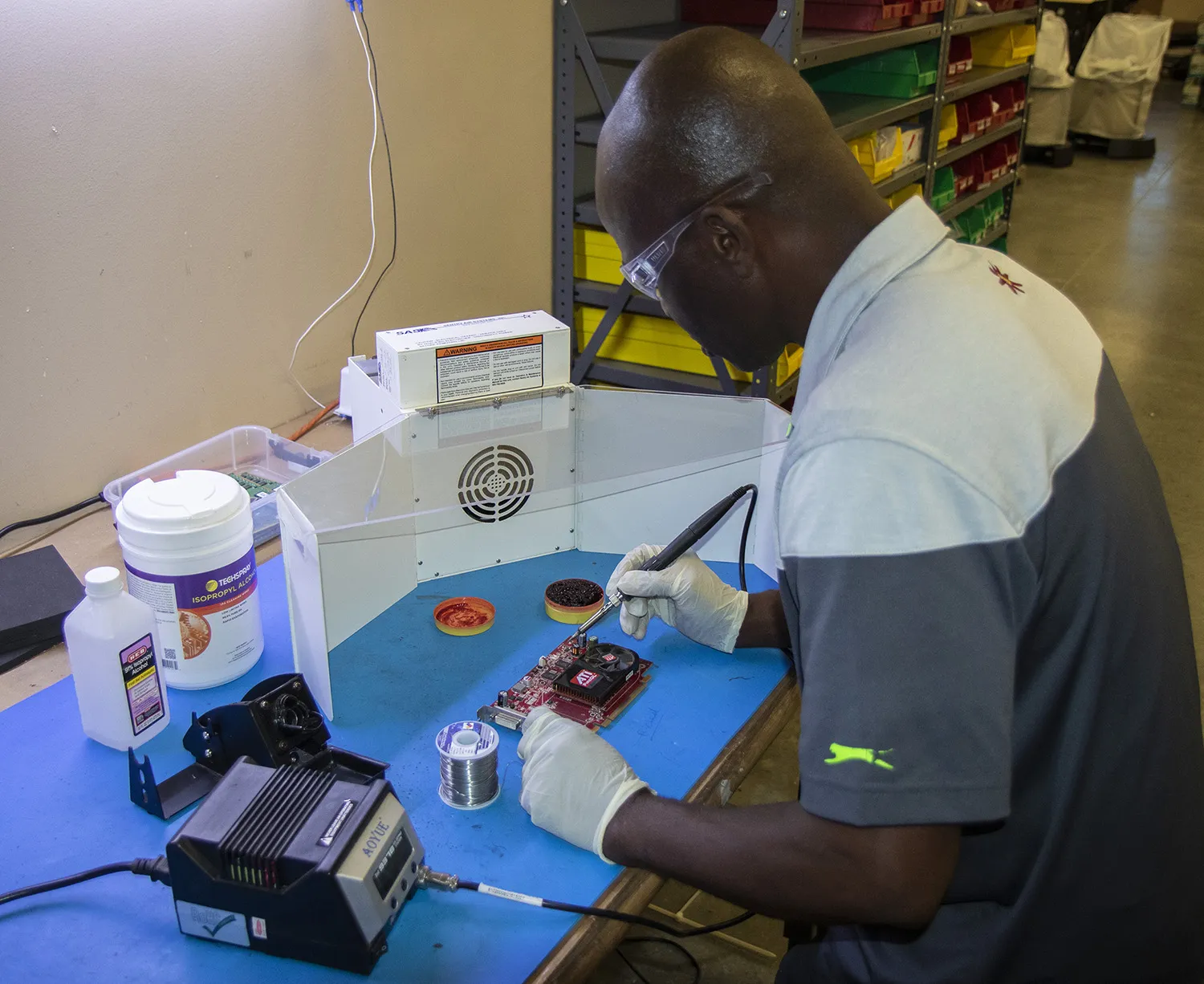
Soldering Safety: Protecting Yourself and Your Work
Soldering safety is non-negotiable when working with ECU PCBs. The process involves high temperatures and potentially harmful fumes, so taking precautions is essential. Here are key safety tips:
- Avoid Burns: Soldering irons can reach temperatures over 300°C (572°F). Always place the iron in a stand when not in use, and never touch the tip.
- Protect Your Eyes: Wear safety glasses to shield your eyes from solder splashes or debris when trimming leads.
- Ventilation: Solder fumes, especially from rosin flux, can irritate your lungs. Work in a well-ventilated area or use a fume extractor to remove harmful vapors.
- Prevent ESD Damage: Electrostatic discharge can destroy sensitive ECU components. Use an anti-static wrist strap and work on an anti-static mat to ground yourself.
- Keep Your Workspace Clean: A cluttered workspace increases the risk of accidents. Keep flammable materials away from your soldering area.
By following these safety practices, you protect yourself and ensure the integrity of the ECU PCB you're working on.
Best Soldering Practices for PCBs
To achieve reliable and long-lasting connections on an ECU PCB, follow these best soldering practices for PCBs. These tips will help you avoid common mistakes and improve your skills over time.
1. Control Temperature and Timing
Overheating can damage components or lift PCB traces. Keep your soldering iron temperature between 280-320°C (536-608°F) for most ECU components. Limit contact time to 3-5 seconds per joint to prevent heat buildup.
2. Use the Right Amount of Solder
Too much solder can create bridges, while too little can result in weak joints. Aim for a small, shiny fillet that covers the pad and component lead without excess buildup. For SMD components, a solder joint should be about 0.2-0.5mm high.
3. Clean Your Tools
A dirty soldering iron tip can lead to poor joints. Clean the tip regularly with a wet sponge or brass wire cleaner while it's hot. Tin the tip (apply a thin layer of fresh solder) after cleaning to prevent oxidation.
4. Inspect and Test Your Work
After soldering, visually inspect each joint under magnification for cracks, cold joints (dull appearance), or bridges. Use a multimeter to test for continuity and ensure there are no short circuits. For ECU PCBs, verify resistance values match the design specifications, typically in the range of 1-10 ohms for certain connections.
5. Practice Patience
Soldering small components on an ECU PCB requires focus. Take your time to align components and apply solder precisely. Rushing can lead to mistakes that are harder to fix later.
Common Soldering Mistakes and How to Fix Them
As a beginner, you're likely to encounter a few hiccups while soldering ECU PCB components. Here are some common issues and solutions:
- Cold Solder Joints: These appear dull and grainy, indicating a weak connection. Reheat the joint and add a small amount of fresh solder to create a shiny, smooth finish.
- Solder Bridges: Excess solder can connect adjacent pads or pins, causing shorts. Use a desoldering wick and flux to remove the excess solder carefully.
- Lifted Pads: Applying too much heat or force can lift the copper pad from the PCB. If this happens, use a small wire to bridge the connection to a nearby trace, securing it with solder.
- Component Misalignment: If an SMD component shifts during soldering, desolder it using a hot air rework station or wick, then reposition and resolder it.
Learning to identify and correct these issues will build your confidence and improve the quality of your ECU PCB projects.
Tips for Working Specifically on ECU PCBs
ECU PCBs are unique due to their compact design and critical role in vehicle systems. Here are some tailored tips for soldering on these boards:
- Work in Small Sections: ECU PCBs often have densely packed components. Focus on soldering one area at a time to avoid mistakes.
- Check Component Ratings: Automotive components must withstand heat, vibration, and voltage fluctuations. Verify that replacement parts match the original specifications, such as a capacitor rated for 16V or higher in typical ECU circuits.
- Avoid Overheating Sensitive Chips: Microcontrollers and sensors on ECU PCBs are heat-sensitive. Use a heat sink or lower temperature (around 280°C/536°F) when soldering near these components.
- Test After Each Repair: After soldering, test the ECU in a controlled environment to ensure functionality before reinstalling it in a vehicle.
Building Skills Through Practice
Soldering is a skill that improves with hands-on experience. Start with practice kits or old PCBs before working on a real ECU board. Focus on perfecting your technique for both through-hole and SMD components. Over time, you'll develop a steady hand and an eye for quality joints.
Consider timing yourself to see how long it takes to solder a set of components. For example, soldering 10 through-hole resistors should take about 10-15 minutes as a beginner. With practice, you can reduce this to under 5 minutes while maintaining precision.
Conclusion: Start Soldering with Confidence
Soldering components on an ECU PCB may seem challenging at first, but with the right tools, techniques, and safety practices, you can achieve professional results. This guide has covered the essentials of soldering ECU PCB components, from SMD soldering for beginners to through-hole soldering techniques. We've also highlighted soldering safety and best soldering practices for PCBs to help you work efficiently and securely.
As you embark on your soldering journey, remember that patience and practice are key. Each joint you create brings you closer to mastering this valuable skill. With time, you'll be able to tackle complex ECU repairs and designs, contributing to reliable automotive systems. Get started today, and watch your confidence grow with every successful connection.


