 ALLPCB


Rigid-flex printed circuit boards (PCBs) are transforming the electronics landscape, particularly in high-stakes industries like aerospace and medical devices. These hybrid boards combine the structural stability of rigid PCBs with the adaptability of flexible circuits, enabling compact, reliable, and lightweight designs. For engineers, mastering rigid-flex PCB design is critical to meeting the stringent demands of these applications, from withstanding extreme vibrations in avionics to ensuring biocompatibility in implantable medical devices. In this blog, we explore key design strategies to optimize rigid-flex PCBs for aerospace and medical applications, offering practical insights to enhance performance and reliability.
Why Rigid-Flex PCBs Matter in Aerospace and Medical Devices
Rigid-flex PCBs are uniquely suited for aerospace and medical applications due to their ability to reduce size, weight, and potential failure points. In aerospace, where every gram impacts fuel efficiency, rigid-flex PCBs eliminate bulky connectors and cables, reducing weight by up to 60% compared to traditional rigid PCB assemblies. For medical devices, such as pacemakers or wearable monitors, their flexibility allows integration into compact, body-conforming designs while maintaining high reliability. The global rigid-flex PCB market is projected to reach USD 77.7 billion by 2034, driven by demand for miniaturization and durability in these sectors.
Key Design Considerations for Rigid-Flex PCBs
Designing rigid-flex PCBs requires a balance of electrical, mechanical, and environmental considerations. Below, we outline critical strategies to ensure optimal performance.
1. Material Selection for Durability and Flexibility
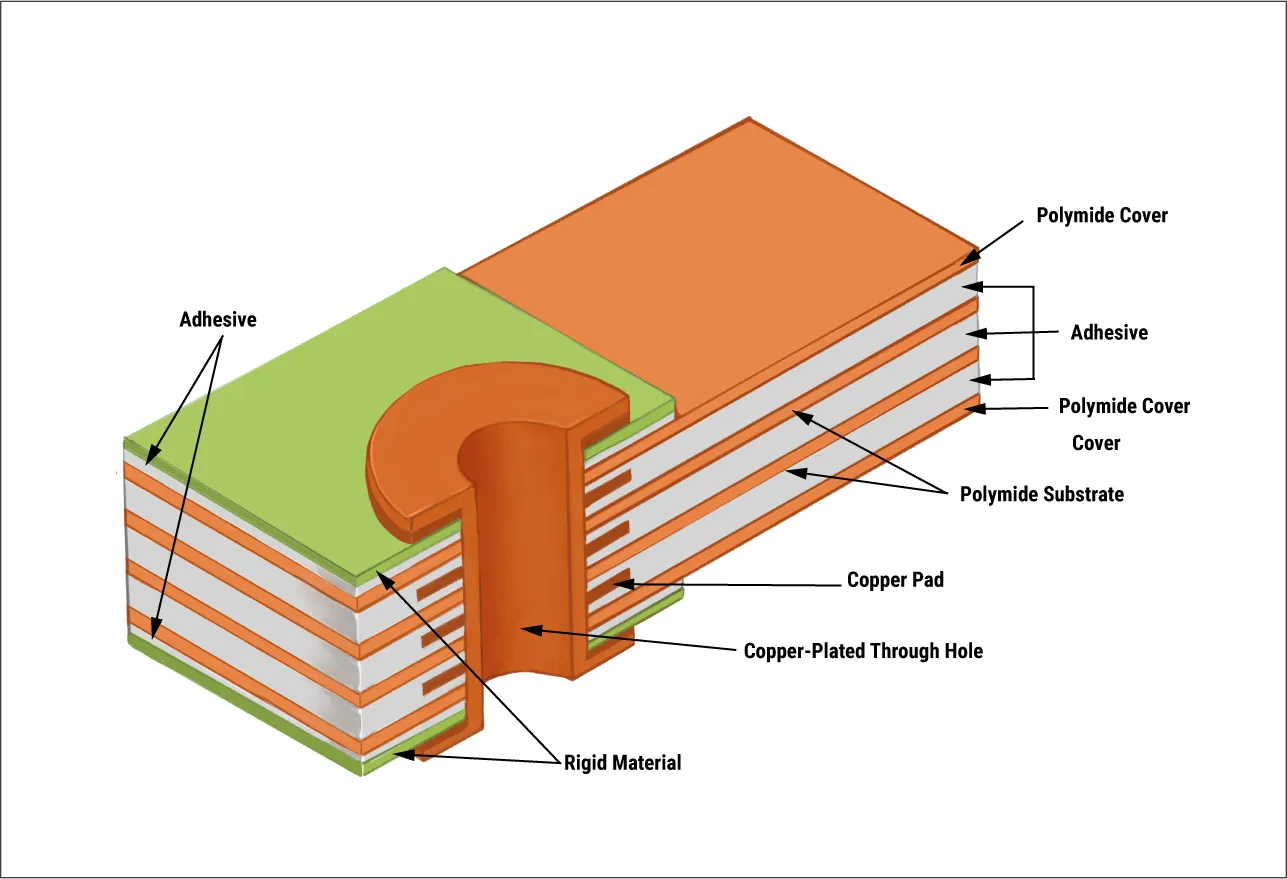
Choosing the right materials is foundational to rigid-flex PCB success. Polyimide is the most common flexible substrate due to its thermal stability (operating from -200'C to 400'C) and chemical resistance. For rigid sections, FR4 is standard, but high-frequency applications in aerospace may require low-loss materials like Rogers 4000 series to maintain signal integrity at frequencies above 5 GHz. Copper cladding, typically 1 oz (0.0014" thick), is used for conductors, with rolled annealed copper preferred for dynamic flexing applications to withstand thousands of bend cycles.
Design Tip: Use adhesiveless laminates to enhance via reliability. Adhesives, with a thermal expansion coefficient 10-20 times higher than FR4, can stress vias during thermal cycling, risking cracks in high-temperature aerospace environments.
2. Optimizing Layer Stackup for Signal Integrity
Layer stackup design directly impacts signal integrity and impedance control, critical for high-speed data transmission in aerospace navigation systems or medical imaging devices. A typical rigid-flex PCB might include 4-8 layers, with flexible layers sandwiched between rigid sections. To minimize crosstalk, place signal layers adjacent to ground planes and maintain a consistent dielectric thickness (e.g., 2-3 mils for polyimide). For high-frequency signals, controlled impedance traces (e.g., 50 ohms for single-ended or 100 ohms for differential pairs) are essential.
Design Tip: Stagger traces in flexible sections to reduce stress and prevent cracking. Avoid placing vias in bend areas, keeping them at least 50 mils from the flex-rigid interface to prevent mechanical failure.
3. Bend Radius and Mechanical Design
The bend radius-the minimum radius a flexible section can bend without damage-is a critical parameter. For static applications (flexing <100 times, e.g., during installation), the bend radius should be 10 times the board thickness. For dynamic applications (e.g., robotic surgical tools), it should be 100 times the thickness. A 4-layer rigid-flex PCB with a 0.01" thickness, for instance, requires a 1" bend radius for dynamic flexing. Exceeding these limits risks copper trace fractures or delamination.
Design Tip: Use teardrop-shaped vias and large annular rings (>8 mils) to enhance structural integrity against shear forces in bending areas. Incorporate anchors and spurs encapsulated with coverlay to prevent trace lifting.
4. Thermal Management for Harsh Environments
Aerospace and medical devices often operate in extreme conditions, from the -55'C to 125'C range in avionics to the 37'C body environment for implants. Effective thermal management prevents overheating and ensures reliability. Use thermal vias to dissipate heat from high-power components, and consider heat-dissipating substrates like polyimide with enhanced thermal conductivity. For compact medical devices with high power density, integrate thermal pads or heat sinks in rigid sections.
Design Tip: Simulate thermal performance using tools like SPICE or field solvers to predict temperature profiles under operational conditions, ensuring components stay within safe limits (e.g., <85'C for most ICs).

5. Environmental Resilience and Testing
Aerospace and medical applications demand resilience against moisture, corrosion, and mechanical stress. In aerospace, rigid-flex PCBs must withstand vibrations up to 10,000 G-forces in missiles or helicopters. Medical devices require biocompatibility and resistance to sterilization processes. Apply conformal coatings or solder masks to protect against moisture and chemicals, and use stiffeners in rigid sections to support heavy components under vibration.
Design Tip: Conduct rigorous testing, including mechanical stress tests, thermal cycling (-55'C to 125'C for aerospace), and accelerated lifecycle tests for medical implants (simulating 5-10 years of use). These ensure compliance with standards like IPC-2223 for bend radius and FDA regulations for medical devices.
Application-Specific Strategies
Aerospace: Avionics and Satellites
In avionics, rigid-flex PCBs enable compact designs for navigation and communication systems. Their three-dimensional flexibility allows integration into confined aircraft fuselages, reducing the need for connectors and improving reliability by minimizing failure points. For satellites, lightweight rigid-flex PCBs (up to 75% lighter than rigid PCB assemblies) are critical for reducing payload weight. Use high-density interconnect (HDI) techniques, such as microvias (0.004" diameter), to pack more functionality into smaller areas.
Example: A 6-layer rigid-flex PCB in a satellite communication module might use 3 mil traces and spaces to achieve 10 Gbps data rates, with shielding layers to protect against electromagnetic interference (EMI).
Medical Devices: Implants and Wearables
For implantable devices like pacemakers, rigid-flex PCBs offer biocompatibility and space efficiency. Their flexible sections conform to the body's contours, while rigid areas support dense component mounting. In wearables, such as glucose monitors, rigid-flex PCBs enable lightweight, durable designs that withstand daily flexing. Ensure compliance with FDA's Premarket Notification 510(k) by validating biocompatibility and reliability through clinical studies.
Example: A 4-layer rigid-flex PCB in a cochlear implant might use 0.005" polyimide layers to achieve a 0.5" bend radius, with 0201 SMD components for miniaturization.
Challenges and Mitigation Strategies
Rigid-flex PCB design is complex, with challenges like signal integrity, bend radius management, and manufacturing tolerances. To address signal integrity, use simulation tools like Siemens PADS Professional to validate impedance and power integrity. Mitigate bend radius issues by clearly defining bend areas early in the design and adhering to IPC-2223 standards. Collaborate closely with manufacturers to align material selection and layer stackup with fabrication capabilities, reducing risks of warping or misalignment.
Design Tip: Use 3D design tools like Altium Designer to model bending and folding, ensuring the PCB fits the target enclosure without exceeding mechanical limits.
How ALLPCB Supports Rigid-Flex PCB Design
For engineers tackling rigid-flex PCB projects, partnering with a reliable manufacturer is crucial. ALLPCB offers advanced manufacturing capabilities, including quick-turn prototyping (2-4 weeks for rigid-flex PCBs) and global logistics to streamline development. Our ISO9001:2015-certified facilities ensure high-quality production, with 100% electrical testing and AOI/X-ray inspection to meet aerospace and medical standards. Whether you need HDI designs or complex multilayer stackups, our team supports engineers with design-for-manufacturability (DFM) feedback to optimize performance and reduce costs.
Conclusion
Rigid-flex PCBs are indispensable for aerospace and medical devices, offering unmatched flexibility, reliability, and space efficiency. By prioritizing material selection, layer stackup optimization, bend radius management, thermal design, and rigorous testing, engineers can create robust solutions for demanding applications. From avionics to implantable devices, these strategies ensure high performance and compliance with industry standards. As the rigid-flex PCB market grows, staying ahead requires collaboration with experienced manufacturers and advanced design tools to turn innovative concepts into reality.


