 ALLPCB


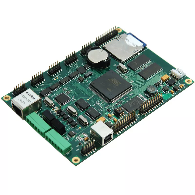
Active components like transistors, diodes, and integrated circuits (ICs) are the heart of printed circuit boards (PCBs), driving functionality in everything from simple gadgets to complex systems. When these components fail, it can lead to frustrating downtime and costly repairs. If you're searching for ways to tackle troubleshooting transistor failures, identifying diode problems in PCBs, understanding common IC faults, or learning active component testing methods, this guide is for you. We'll walk you through practical steps to diagnose and resolve issues with active components on your PCB, ensuring you get your projects back on track quickly.
In this comprehensive blog post, we'll break down the common causes of active component failures, provide actionable troubleshooting techniques, and share testing methods to pinpoint issues. Whether you're an engineer, hobbyist, or technician, you'll find valuable insights to help you navigate these challenges with confidence.
Understanding Active Components in PCBs
Active components are parts of a circuit that can amplify, switch, or control electrical signals. Unlike passive components like resistors and capacitors, active components such as transistors, diodes, and ICs require a power source to function. They are critical to the operation of a PCB, but their complexity makes them prone to failure under certain conditions like overheating, overvoltage, or manufacturing defects.
Before diving into troubleshooting, it's important to recognize the role each active component plays:
- Transistors: Act as switches or amplifiers in circuits, controlling current flow.
- Diodes: Allow current to flow in one direction, often used for rectification or protection.
- Integrated Circuits (ICs): Complex chips that combine multiple functions, such as microcontrollers or amplifiers, into a single package.
Failures in these components can cause a range of issues, from complete circuit failure to intermittent performance. Let's explore how to identify and address these problems step by step.
Common Causes of Active Component Failures
Understanding why active components fail is the first step in effective troubleshooting. Here are some of the most frequent causes:
1. Overheating
Excessive heat is a leading cause of failure in active components. For instance, transistors can fail if they dissipate more power than their thermal rating allows. A typical NPN transistor might have a maximum junction temperature of 150°C. Exceeding this can degrade the semiconductor material, leading to permanent damage.
2. Overvoltage or Overcurrent
Applying voltage or current beyond a component's specifications can cause breakdowns. For example, a diode rated for a reverse voltage of 50V will fail if exposed to 60V, often resulting in a short circuit. Similarly, ICs can suffer internal damage from voltage spikes.
3. Mechanical Stress
Physical stress from improper handling, vibration, or poor soldering can crack or dislodge components. This is especially common with surface-mount ICs, where tiny pins can break under stress.
4. Manufacturing Defects
Defects during production, such as impurities in semiconductor materials or poor packaging, can lead to early failures. These issues often manifest as intermittent faults or complete component breakdown shortly after installation.
5. Aging and Wear
Over time, active components degrade due to repeated thermal cycles or electrical stress. For instance, the gain of a transistor might decrease after years of operation, affecting circuit performance.
By recognizing these causes, you can narrow down potential issues during troubleshooting and take preventive measures in future designs.
Troubleshooting Transistor Failures
Transistors are vital for amplification and switching, but they are sensitive to heat, voltage, and current stress. When troubleshooting transistor failures, follow these steps to identify and resolve issues:
Step 1: Visual Inspection
Start by examining the transistor for physical damage. Look for burn marks, cracks, or bulging on through-hole or surface-mount transistors. These signs often indicate overheating or overcurrent damage.
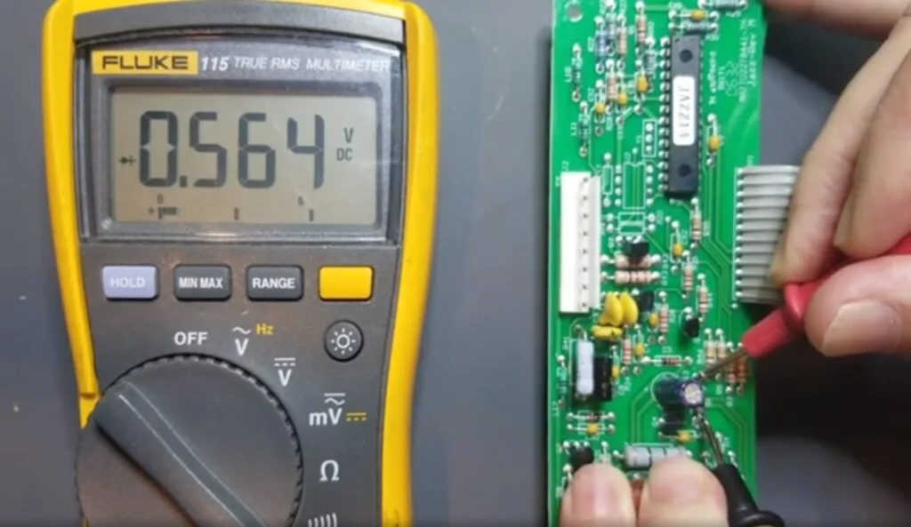
Step 2: Test with a Multimeter
Use a multimeter in diode mode to check for shorts or open circuits. For an NPN transistor, place the positive lead on the base and the negative lead on the emitter or collector. You should see a voltage drop of about 0.6V to 0.7V if the transistor is functioning. No reading or a very low resistance indicates a failure.
Step 3: Check Surrounding Components
A failed transistor might be a symptom of a larger issue, like a shorted capacitor or a malfunctioning voltage regulator. Measure the input voltage at the transistor's collector to ensure it matches the circuit's design specs, typically between 5V and 24V in common applications.
Step 4: Replace and Test
If the transistor tests faulty, replace it with one of the same specifications (e.g., matching current gain or hFE value). After replacement, power up the circuit and monitor for proper operation using an oscilloscope to check signal output if possible.
Identifying Diode Problems in PCBs
Diodes are simpler than transistors but can still fail, often causing circuit-wide issues. When identifying diode problems in PCBs, focus on these practical steps:
Step 1: Look for Physical Damage
Inspect the diode for discoloration or cracks, which can indicate overheating or overvoltage damage. A burned smell near the component is another red flag.
Step 2: Test Forward and Reverse Bias
Use a multimeter in diode mode to test the component. In forward bias (positive lead on anode, negative on cathode), you should see a voltage drop of 0.6V to 0.7V for silicon diodes or 0.2V to 0.3V for Schottky diodes. In reverse bias, there should be no conduction (infinite resistance). A reading in both directions suggests a short, while no reading at all indicates an open circuit.
Step 3: Check for Circuit Impact
A failed diode can disrupt power supply circuits or protection mechanisms. For instance, a shorted diode in a rectifier circuit might cause excessive current flow, damaging other components. Measure the voltage across nearby components to identify cascading effects.
Step 4: Replace with Correct Ratings
Replace a faulty diode with one that matches the original's voltage and current ratings. For example, if the original was a 1N4007 rated for 1000V and 1A, ensure the replacement meets or exceeds these specs.
Common IC Faults and How to Diagnose Them
Integrated circuits are complex, making common IC faults harder to diagnose. These chips can fail due to internal shorts, pin damage, or incorrect power supply conditions. Here's how to approach troubleshooting:
1. Power Supply Issues
Many IC failures stem from incorrect voltage or current. For instance, a microcontroller IC rated for 3.3V will fail if supplied with 5V. Use a multimeter to verify the voltage at the IC's power pins matches the datasheet specifications.
2. Pin Damage or Poor Connections
Check for bent or broken pins, especially on through-hole ICs, or poor soldering on surface-mount chips. Reflow solder joints if necessary, using a soldering iron with a fine tip and flux to ensure a clean connection.
3. Overheating
ICs often fail due to inadequate heat dissipation. If an IC feels hot to the touch or shows thermal shutdown behavior (intermittent operation), add a heatsink or improve airflow around the component.
4. Functional Testing
Use an oscilloscope to check input and output signals at the IC's pins. For example, if testing a 555 timer IC, confirm that the output pin produces a square wave with the expected frequency (e.g., 1kHz based on resistor and capacitor values in the circuit).
Active Component Testing Methods
Accurate diagnosis relies on the right active component testing methods. Here are some proven techniques to test transistors, diodes, and ICs effectively:
1. Multimeter Testing
A multimeter is the go-to tool for basic testing. Set it to diode or continuity mode to check transistors and diodes for shorts or open circuits. For ICs, measure voltage at power and ground pins to ensure proper supply.
2. Oscilloscope Analysis
An oscilloscope helps analyze dynamic signals. For transistors in amplifier circuits, check if the output waveform matches the expected gain. For ICs, verify clock signals or data outputs at specific pins.
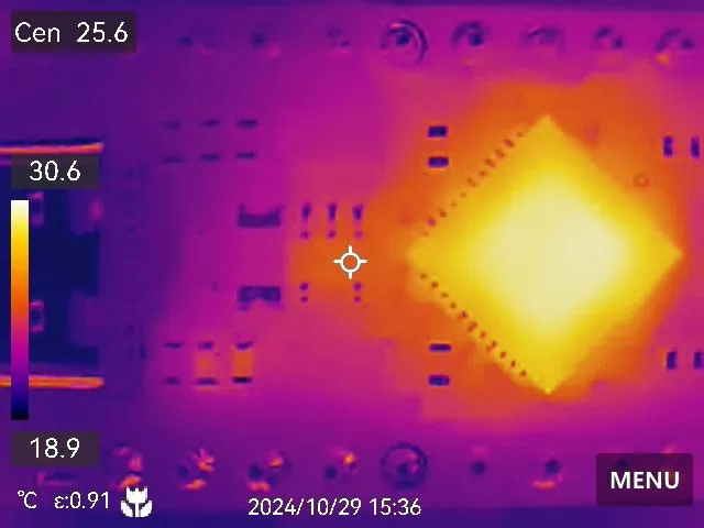
3. Thermal Imaging
A thermal camera can detect overheating components. If a transistor or IC shows a temperature spike (e.g., above 100°C when idle), it may be failing or operating outside its limits.
4. Component Testers
Dedicated component testers, such as transistor or IC testers, provide quick diagnostics. These devices can identify pin configurations and measure parameters like current gain for transistors or logic states for ICs.
5. In-Circuit Testing
For complex PCBs, in-circuit testing (ICT) uses specialized equipment to check components without desoldering. This method is ideal for detecting faults in densely populated boards where removing components is risky.
Preventing Active Component Failures in Future Designs
While troubleshooting is essential, preventing failures saves time and resources. Consider these tips for your next PCB design:
- Use Proper Ratings: Select components with voltage, current, and power ratings at least 20% higher than the circuit's maximum expected values.
- Add Protection Circuits: Include overvoltage protection diodes or transient voltage suppressors to shield sensitive ICs and transistors.
- Improve Thermal Management: Use heatsinks, thermal pads, or adequate PCB copper planes to dissipate heat from high-power components.
- Follow Best Soldering Practices: Avoid cold solder joints by using the correct temperature (typically 300°C for lead-free solder) and ensuring clean connections.
- Test Before Deployment: Perform burn-in testing on new designs to identify early failures under controlled stress conditions.
Conclusion
Troubleshooting active component failures in PCBs doesn't have to be daunting. By understanding the common causes of failure, mastering techniques for troubleshooting transistor failures, identifying diode problems in PCBs, diagnosing common IC faults, and applying effective active component testing methods, you can quickly restore functionality to your circuits. Tools like multimeters, oscilloscopes, and thermal cameras are invaluable allies in this process, helping you pinpoint issues with precision.
At ALLPCB, we’re committed to supporting engineers and hobbyists with high-quality PCB solutions and resources. Whether you're debugging a prototype or repairing a production board, the practical steps outlined in this guide will help you tackle active component failures with confidence. Keep these tips in mind for your next project to minimize issues and ensure long-lasting performance.


