ALLPCB


Are you looking to optimize your SMT soldering process for unique PCB projects? Programming custom reflow profiles is the key to achieving precise control over your reflow oven, ensuring perfect solder joints and protecting sensitive components. In this comprehensive guide, we’ll walk you through the process of creating tailored reflow profiles, using SMT soldering code, and mastering reflow equipment control. Whether you're working on intricate PCB programming projects or fine-tuning profile creation, this blog will provide actionable insights to elevate your soldering game.
Why Custom Reflow Profiles Matter for PCB Projects
Reflow soldering is a critical step in surface-mount technology (SMT) assembly, where components are attached to a printed circuit board (PCB) using solder paste that melts and solidifies under controlled heat. Standard reflow profiles may work for generic projects, but unique PCB designs often require specific temperature curves to avoid issues like thermal shock, incomplete soldering, or component damage. Custom reflow profiles allow you to tailor the heating and cooling phases to match the needs of your board’s materials, components, and layout.
For instance, a board with densely packed micro-components may need a slower ramp-up rate to prevent overheating, while a board with larger components might require a longer soak time to ensure even heat distribution. By programming a custom profile, you gain precise control over the thermal process, resulting in higher-quality solder joints and fewer defects.
Understanding the Basics of a Reflow Profile
Before diving into programming custom reflow profiles, let’s break down the standard structure of a reflow profile. A typical profile consists of four main phases:
- Preheat Phase: The temperature rises gradually, typically from room temperature to 150°C, at a rate of 1-3°C per second. This phase activates the flux in the solder paste and prevents thermal shock to components.
- Soak Phase: The temperature is held steady between 150°C and 180°C for 60-120 seconds. This ensures even heating across the board and prepares the solder paste for melting.
- Reflow Phase: The temperature peaks, often between 220°C and 250°C, for 20-40 seconds. This is when the solder paste melts and forms joints with the components and PCB pads.
- Cooling Phase: The temperature drops at a controlled rate of 2-4°C per second to solidify the solder joints without causing stress or cracks.
These parameters vary based on the solder paste type (lead-free or leaded), component specifications, and board design. Customizing these phases through programming allows you to adapt the profile to your specific project needs.
Steps to Programming Custom Reflow Profiles
Creating a custom reflow profile involves understanding your project’s requirements, selecting the right equipment, and programming the oven with precise temperature and time settings. Here’s a step-by-step guide to help you through the process of profile creation.
Step 1: Analyze Your PCB Project Requirements
Start by reviewing the specifications of your PCB and components. Consider factors like:
- The type of solder paste (e.g., lead-free solder often requires higher peak temperatures around 235-250°C).
- Component thermal limits (check datasheets for maximum temperature tolerances, often between 240-260°C for most SMT parts).
- Board size and thickness (larger or thicker boards may need longer soak times for even heating).
For example, if your project includes sensitive components like microcontrollers with a max temperature of 245°C, you’ll need to cap the reflow peak below this threshold to avoid damage.
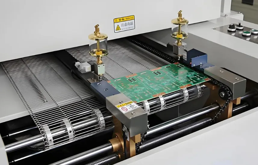
Step 2: Choose the Right Reflow Equipment
Modern reflow ovens come with programmable controllers that allow you to input custom temperature profiles. Ensure your equipment supports multiple zones or stages for precise control over each phase. Some ovens also offer software interfaces for easier profile creation and storage, which is ideal for managing multiple PCB programming projects.
Step 3: Use SMT Soldering Code for Profile Programming
Many reflow ovens allow programming through a built-in interface or external software. If your equipment supports custom code, you can define the temperature and time for each phase with precision. Below is a simplified example of how SMT soldering code might look for a basic custom profile (syntax varies by equipment):
SET_PREHEAT_TEMP 150 SET_PREHEAT_RATE 2 SET_SOAK_TEMP 180 SET_SOAK_TIME 90 SET_REFLOW_TEMP 235 SET_REFLOW_TIME 30 SET_COOL_RATE 3
This code sets a preheat target of 150°C with a ramp rate of 2°C per second, a soak at 180°C for 90 seconds, a reflow peak at 235°C for 30 seconds, and a cooling rate of 3°C per second. Adjust these values based on your project’s needs and test the profile with a small batch to ensure accuracy.
Step 4: Test and Refine the Profile
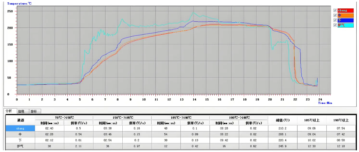
After programming the profile, run a test with a sample board. Use a thermocouple or thermal profiler to monitor the actual temperatures across different zones of the PCB. Compare the recorded data with your target profile and adjust as needed. For instance, if the soak phase shows uneven heating (e.g., a 10°C difference between board edges and center), extend the soak time by 20-30 seconds.
Best Practices for Reflow Equipment Control
Effective reflow equipment control is essential for consistent results. Here are some tips to ensure your custom profiles perform optimally:
- Calibrate Regularly: Over time, oven sensors may drift, leading to inaccurate temperatures. Calibrate your equipment monthly using a certified thermal profiler to maintain precision within ±2°C.
- Monitor Airflow: Uneven airflow can cause temperature inconsistencies. Ensure the oven’s convection system is functioning properly, especially for densely populated boards.
- Store Profiles Data: Save successful custom reflow profiles in your oven’s memory or software for reuse in future PCB programming projects. Label them clearly, e.g., “Profile_LeadFree_ThinBoard_235C.”
Common Challenges in Custom Reflow Profile Creation
While programming custom profiles offers flexibility, it also comes with challenges. Here are some common issues and how to address them:
Thermal Shock and Component Damage
If the preheat ramp rate is too fast (e.g., above 3°C per second), components may experience thermal shock, leading to cracks or failures. Solve this by reducing the rate to 1-2°C per second and extending the preheat phase to 90-120 seconds.
Incomplete Solder Joints
Inadequate soak or reflow time can result in unmelted solder paste, causing weak joints. Ensure the soak phase lasts at least 60 seconds and the reflow peak reaches the solder paste’s melting point (e.g., 217°C for common lead-free pastes) for a minimum of 20 seconds.
Overheating Sensitive Components
Exceeding a component’s maximum temperature (often listed as 240-250°C in datasheets) can cause internal damage. Always set the reflow peak 5-10°C below the lowest tolerance of your board’s components.
Advanced Tips for PCB Programming Projects
For engineers working on complex PCB programming projects, consider these advanced strategies to further refine your custom reflow profiles:
- Use Multi-Zone Profiles Adjustments: If your oven supports multiple heating zones, program slight variations in temperature across zones to compensate for board layout differences. For example, increase heat by 5°C in zones near large components to ensure proper soldering.
- Integrate Software Tools: Some reflow systems allow integration with design software to simulate thermal behavior before soldering. This can help predict potential issues and optimize profile creation.
- Batch Testing: For production runs, test your custom profile on a small batch (e.g., 5-10 boards) and inspect solder joints under a microscope. Look for issues like voids or insufficient wetting, and tweak the profile accordingly.
How Custom Profiles Creation Boosts Efficiency
Investing time in custom reflow profile creation pays off in the long run. By tailoring profiles to specific projects, you reduce the risk of rework, minimize component damage, and improve overall yield. For high-volume production, a well-optimized profile can save hours of troubleshooting and thousands of dollars in defective boards. Even for prototypes, custom profiles ensure consistency, making it easier to scale up to full production.
For example, a project using a lead-free solder paste with a melting point of 217°C might fail with a generic profile peaking at 210°C. By programming a custom profile with a peak of 235°C, you ensure proper melting and strong joints, reducing defect rates from 10% to under 1%.
Conclusion: Take Control of Your SMT Soldering Process
Programming custom reflow profiles is a powerful way to tailor your oven’s performance to the unique needs of your PCB projects. By mastering SMT soldering code, refining reflow equipment control, and following best practices for profile creation, you can achieve reliable, high-quality results every time. Whether you’re working on small-scale prototypes or large production runs, the ability to customize your reflow process gives you a competitive edge in electronic manufacturing.
Start by analyzing your project requirements, programming a test profile, and refining it based on real-world data. With practice, you’ll develop a library of custom profiles that streamline your workflow and ensure consistent soldering success. At ALLPCB, we’re committed to supporting your PCB assembly journey with expert resources and services to bring your designs to life.