 ALLPCB


If you're looking to master axial lead through-hole assembly for your PCB projects, you've come to the right place. This guide will walk you through the essentials of axial lead component insertion, soldering techniques, forming tools, PCB design rules, and troubleshooting tips. Whether you're a beginner or an experienced engineer, you'll find practical advice to improve your skills and ensure reliable results. Let's dive into the details of this critical process in electronics manufacturing.
What Is Axial Lead Through-Hole Assembly?
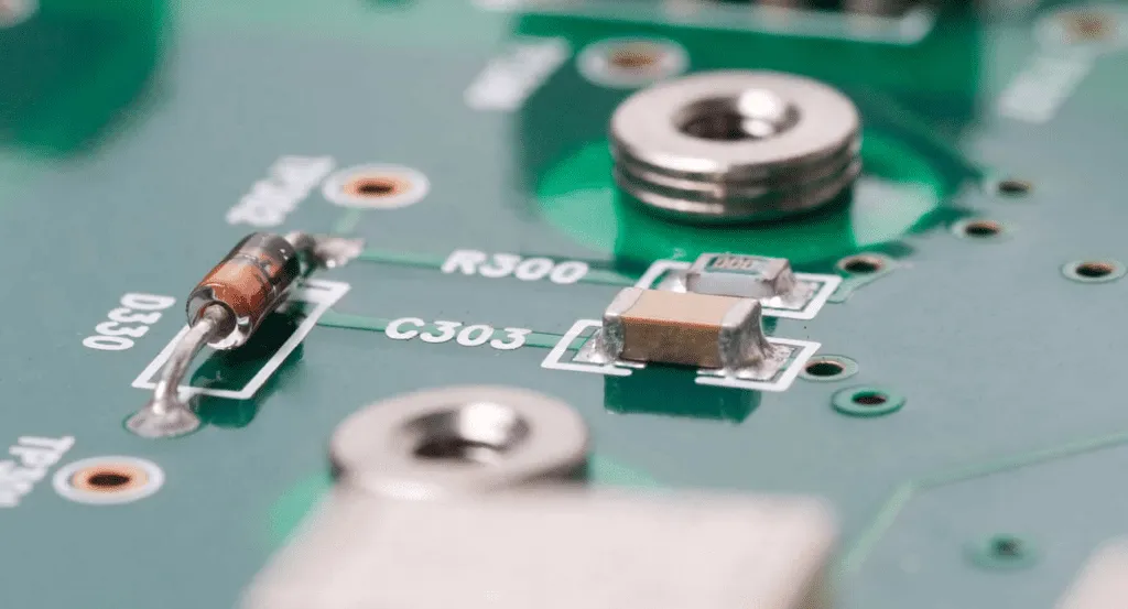
Axial lead through-hole assembly is a traditional method of mounting electronic components onto a printed circuit board (PCB). Unlike surface-mount technology, through-hole assembly involves inserting component leads through pre-drilled holes in the PCB and soldering them on the opposite side. Axial lead components, such as resistors and capacitors, have leads that extend from both ends of the component body, running parallel to its axis. This design makes them ideal for applications requiring durability and high reliability, such as in industrial equipment or aerospace systems.
Through-hole technology remains relevant due to its strong mechanical bonds, ease of manual assembly, and suitability for high-power or high-stress environments. In this guide, we'll cover every aspect of working with axial lead components to help you achieve professional-grade assemblies.
Understanding Axial Lead Components
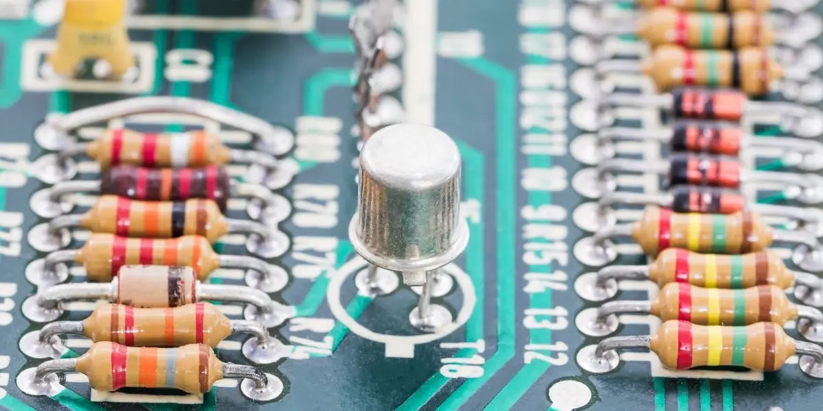
Before diving into assembly techniques, it's important to understand axial lead components. These components typically include resistors, capacitors, diodes, and inductors. Their leads are positioned on opposite ends, making them easy to insert into PCB holes. Axial leads are often preferred in through-hole assembly because they can handle higher current and voltage compared to surface-mount alternatives, with typical power ratings for resistors ranging from 0.25W to 2W.
These components are also easier to replace or rework, which is why they are common in prototyping and repair work. However, their larger size compared to surface-mount components means they take up more space on a PCB, which can be a limitation in compact designs.
Step-by-Step Guide to Axial Lead Component Insertion
Proper axial lead component insertion is the foundation of a successful through-hole assembly. Follow these steps to ensure accuracy and reliability:
- Prepare the PCB: Ensure the PCB has the correct hole sizes for your components. Standard hole diameters for axial leads range from 0.7mm to 1.0mm, depending on the lead thickness. Clean the board to remove any dust or debris that could affect soldering.
- Identify Component Orientation: Check the component's polarity (if applicable, such as with diodes or electrolytic capacitors) to ensure correct placement. Incorrect orientation can lead to circuit failure.
- Insert the Component: Gently push the axial leads through the designated holes from the top side of the PCB. The component body should sit flush against the board unless specified otherwise in the design.
- Bend the Leads: On the underside of the PCB, bend the leads slightly outward to hold the component in place before soldering. Avoid excessive bending, as it can stress the leads and cause them to break.
Axial Lead Forming Tools: Shaping for Precision
Forming axial leads before insertion is often necessary to ensure a snug fit and prevent damage during assembly. Using the right axial lead forming tools can save time and improve consistency. Here are some essential tools and their uses:
- Lead Forming Pliers: These pliers have specialized jaws to bend leads at precise angles, typically 90 degrees, for a clean fit against the PCB. They are ideal for high-volume assembly tasks.
- Lead Bending Jigs: These are templates or fixtures that help form multiple leads to the same shape and length. They are especially useful for ensuring uniformity in production runs.
- Cutting Tools: After soldering, excess lead length needs to be trimmed. Flush cutters with fine tips are perfect for this, leaving a clean finish without damaging the solder joint.
Using these tools, you can form leads to match the PCB's hole spacing, which is often standardized at 2.54mm (0.1 inches) for through-hole designs. Properly formed leads reduce the risk of short circuits and improve the overall look of the assembly.

Axial Lead Soldering Techniques for Strong Connections
Soldering is a critical step in axial lead through-hole assembly. Poor soldering can lead to weak joints, intermittent connections, or component failure. Here are some proven axial lead soldering techniques to ensure strong, reliable connections:
- Use the Right Soldering Iron: A soldering iron with a fine tip (1mm or smaller) and adjustable temperature (around 300°C for lead-based solder and 350°C for lead-free solder) is ideal for through-hole components.
- Apply Flux: Flux cleans the leads and PCB pads, improving solder flow. Apply a small amount of flux to the joint before soldering to prevent oxidation.
- Solder Quickly: Touch the soldering iron tip to the lead and pad simultaneously, then apply solder. The process should take no more than 2-3 seconds per joint to avoid overheating the component. A good joint will have a shiny, concave appearance.
- Inspect the Joint: After soldering, check for cold solder joints (dull or cracked appearance) or excess solder that could cause shorts.
For larger production runs, wave soldering can be used. This automated process passes the PCB over a wave of molten solder, ensuring consistent joints for axial lead components. However, for manual assembly or prototyping, hand soldering with the above techniques is often sufficient.
Axial Lead PCB Design Rules for Optimal Performance
Designing a PCB for axial lead components requires careful planning to ensure functionality and ease of assembly. Follow these axial lead PCB design rules to avoid common pitfalls:
- Hole Size and Spacing: Design holes slightly larger than the lead diameter (e.g., 0.8mm hole for a 0.6mm lead) to allow easy insertion without excessive play. Maintain a minimum spacing of 2.54mm between holes to prevent interference.
- Pad Size: Ensure the annular ring (the copper pad around the hole) is at least 0.5mm wider than the hole diameter on each side to provide enough area for soldering.
- Thermal Relief: For components that dissipate heat, such as power resistors, use thermal relief pads to prevent heat from spreading too quickly during soldering, which can cause poor joints.
- Component Placement: Place axial lead components in a uniform orientation (e.g., all resistors aligned horizontally) to simplify assembly and inspection. Avoid placing components too close to board edges to prevent mechanical stress.
Adhering to these design rules minimizes assembly errors and enhances the reliability of the final product. Always double-check your design against the component datasheets to confirm lead dimensions and power ratings.
Image Placement Suggestion: Place an image here showing a PCB layout with axial lead component placements and labeled hole spacing. ALT Text: "PCB design layout for axial lead components"
Troubleshooting Axial Lead Assembly: Common Issues and Fixes
Even with careful preparation, issues can arise during axial lead assembly. Here are some common problems and tips for troubleshooting axial lead assembly:
- Component Not Fitting in Holes: If the leads don’t fit, check if the hole size matches the lead diameter. If the holes are too small, consider re-drilling with a slightly larger bit (e.g., increasing from 0.7mm to 0.8mm). Ensure you're not forcing the component, as this can damage the PCB.
- Cold Solder Joints: A dull or cracked solder joint often indicates insufficient heat. Reheat the joint with a soldering iron at the correct temperature (around 300°C) and add a small amount of fresh solder to ensure a smooth, shiny finish.
- Short Circuits: Excess solder or untrimmed leads can cause shorts. Use flush cutters to trim leads after soldering, and inspect joints with a magnifying glass to remove any solder bridges using a desoldering wick.
- Component Damage: Overheating during soldering can damage sensitive components like diodes. Limit soldering time to 2-3 seconds per joint, and use a heat sink (such as a small alligator clip) on the lead between the component body and the joint to absorb excess heat.
Regular inspection after each assembly step can catch issues early. Using a multimeter to test continuity and resistance (e.g., ensuring a resistor reads close to its rated value, such as 1kΩ ±5%) can also help identify problems before powering up the circuit.
Advantages of Axial Lead Through-Hole Assembly
Despite the rise of surface-mount technology, axial lead through-hole assembly offers several advantages:
- Durability: The mechanical strength of through-hole soldering makes it ideal for components subjected to vibration or stress, with typical shear strength exceeding 10N per joint.
- Ease of Repair: Axial lead components are easier to desolder and replace compared to tiny surface-mount parts, making them a favorite for prototyping and repair work.
- High Power Handling: These components can handle higher currents and voltages, often up to 50V or more for capacitors, making them suitable for power electronics.
These benefits ensure that through-hole assembly remains a valuable skill in electronics manufacturing, especially for high-reliability applications.
Best Practices for Consistent Results
To achieve consistent results with axial lead through-hole assembly, consider these best practices:
- Maintain a Clean Workspace: Keep your work area free of debris to prevent contamination of solder joints or PCB surfaces.
- Use Quality Materials: Invest in high-quality solder (e.g., 60/40 tin-lead or lead-free options with 3% silver content) and components to ensure reliable connections.
- Practice Regularly: Soldering and lead forming are skills that improve with practice. Start with simple kits or scrap boards to build confidence before tackling complex projects.
- Document Your Process: Keep notes on hole sizes, soldering temperatures, and component orientations for future reference, especially for repeat projects.
Conclusion: Elevate Your Axial Lead Assembly Skills
Mastering axial lead through-hole assembly is a valuable skill for any electronics enthusiast or professional. By understanding the basics of axial lead component insertion, using the right forming tools, applying effective soldering techniques, following PCB design rules, and knowing how to troubleshoot issues, you can create durable and reliable PCB assemblies. Whether you're working on a small prototype or a large-scale production run, these techniques will help you achieve consistent, high-quality results.
At ALLPCB, we're committed to supporting your electronics projects with resources and expertise. Use this guide as a starting point to refine your skills and tackle even the most challenging axial lead assembly tasks with confidence.


